Tuesday, August 22, 2023

Stuff

Well, 2022 came and went without a post from me, and I apologize.  Oh, and most of 2023.  Sorry.

I had plans, honest.  I still have plans actually and maybe sometime in what remains of this year I can actually do something about them.

I started posting on Mastodon (if that means anything) you can check it out right here, I sometimes post more than once a month, can you even stand it?

I started writing this post back in June, intending to publish it on the third anniversary of the shuttering of LCM+L, but I couldn't think of anything to say that wouldn't get me immediately sued by The Allen Estate (hallowed be its name) and/or Vulcan so I'll just say that it sure is a darn shame that the place hasn't reopened and I'm sure the current owner has the best of intentions.

Anyway.

ANYWAY.

I do have some new projects in progress and coming down the pike, so to speak.

Xerox Dolphin 

(For a bit more background on the Dolphin, see my previous post here about it.)

After many months I've finally made significant progress getting the Dolphin to boot over its 3mbit Ethernet interface!

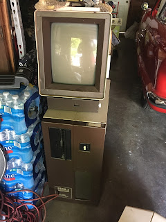
Xerox 1100 (Dolphin) console

It doesn't really look like much, but that picture to the left is the Dolphin (aka 1100, aka D0) after successfully booting into the Alto Net Executive.  (At the same time I got the thing to boot, I learned that my console has no vertical deflection (more on that later)). 

The Dolphin can boot from either 3mbit Ethernet or from the internal hard disk (a 24mb Shugart SA-4008, with 14" platters).  I've been working on updating the IFS implementation (which I started working on while at LCM, long may it stand) to support the new protocols needed to support bootstrapping D0's.  Turns out this only actually requires one new protocol, everything else uses standard PUP services that I'd already implemented to support Alto systems.

That new protocol is "MicrocodeBootRequest" and it's used by the Dolphin's microcode ROM to bring down the "Initial" microcode from the network.  Initial does some hardware testing and initialization, and then initiates another MicrocodeBootRequest, this time to load so-called "emulator" microcode.  This is the final microcode loaded at boot, and its job is to "emulate" (that is, implement) the instruction set that the real software for the system runs on.  On the Dolphin, there were a variety of options, but typically this was either Alto (which emulates the Alto's Nova-based instruction set) or Mesa, which executes the Mesa instruction set.  The Dolphin Alto emulator microcode was primarily used as a bootstrap into other systems (Smalltalk, for example) or for running common Alto utilities to transfer files or copy disks.

The MicrocodeBootRequest protocol is so simple the only documentation for it is less than a paragraph long:

"For version 1 of the protocol, a server willing to supply the data simply sends a sequence of packets of type MicrocodeReply as fast as it can.  The high half of its pupID contains the version number (1) and the low half of the pupID contains the packet sequence number. After all the data packets have been sent, the server sends an empty (0 data bytes) packet for an end marker.  There are no acknowledgments. This protocol is used by Dolphins and Dorados. Currently, the version 1 servers send packets containing 3 * n words of data.  This constraint is imposed by the Rev L Dolphin EPROM microcode.  I’d like to remove this restriction if I get a chance, so please don’t take advantage of it unless you need to.  The Rev L Dolphin EPROM also requires the second word of the source socket to be 4. / HGM May - 80."

Seems simple enough, right?  It took me about five minutes to put together the initial implementation and... it didn't work.  Looked it over, fixed a couple of small things -- still, no joy.  Pulled hair for an entire evening and even that didn't help.

So I went to go looking for the Rev L Dolphin EPROM microcode sources and a friend of mine hooked me up (these sources have since been released publicly in CHM's PARC archives here).  And there, right there, near the beginning of the Ethernet input routine, was this:


"skip over first packet?"  What fresh hell is this?  But sure enough, I changed my implementation to spit out a garbage packet before beginning the actual transfer... and it worked!  The MP codes on the front panel of the D0 changed as Initial started a series of short diagnostic tests.

Front panel of the 1100, showing an MP code of 702

It stopped at "0702," which translates to "Bad Map" per the available documentation.  The map is a 16KW RAM used by the memory mapping hardware to provide address translation; essentially a lookup table for virtual to physical address mappings.  A failure here would seem to point to a bad ram chip or two (which is not at all uncommon for the 4116 RAMs used in this thing) but it turned out to be the power supply -- the 12V supply had gone away, and 4116s require a 12V supply to function.  (It took me *way* too long to find this, and I'm still kind of embarrassed about it.)

I tracked the cause of the loss of 12V to a shorted electrolytic capacitor on one of the 96KW memory boards, and after replacing it all was good -- the tests in the "Initial" microcode finished without errors, and it progressed up to MP code 758, which means: "Trying to load AltoD0.eb from the Ethernet."  Unfortunately it never continued past that -- the D0 would indeed request AltoD0.eb from my IFS, and IFS would happily send it, but the boot process never went any further.

HP 1670D Logic Analyzer lashed up
And this is where I remained stuck until July 2023.  I'd considered a number of options, but ultimately what I needed to be able to see was what the microcode was actually doing when the boot failed.  Much like on the Alto, the D0's backplane offers an array of test points that let me look at the current microcode instruction address, and most (but not all) of the microcode instruction word being executed.  I rigged up the logic analyzer to capture this data, but the major issue was being able to decipher the instruction stream from a raw dump of the bits.

I started writing a disassembler for Dolphin microinstructions and made some small progress with it, but the instruction stream was still rather difficult to decipher.  And then it occurred to me: You dummy, you have the original source code for the boot ROM, it's in the CHM archive.  What if the archive also has the original Alto programs used to assemble those sources?  What if you could use those tools to produce a listing as well?  Then all you'd need would be the microcode instruction addresses from your logic analyzer captures, and you could see *exactly* what was being executed at the source level... with context!

ContrAlto running MicroD
Well, the idea had merit, I gotta admit.  And, as it turns out, the CHM archive did indeed have the D0 microcode assembler (called MicroD), and so it was time to whip out my other pet project, ContrAlto to do the heavy lifting.  The result is available here (the archive contains both the sources and an Alto disk image containing all the necessary tools and sources to rebuild everything for all three stages of microcode boot.)

After all that faffing about, now I had a set of listing files that looked like this:

MicroD 9.14 (OS 16) of March 25, 1981
  at 18-Jul-95 20:15:41

MicroD.run/o/m Sa4000Boot EtherBoot Boot


Sa4000Boot.DIB   302b instructions   written 18-Jul-95 20:14:37
EtherBoot.DIB    222b instructions   written 18-Jul-95 20:14:10
Boot.DIB         356b instructions   written 18-Jul-95 20:13:48

Total of 1102b instructions

Checking for errors...
Linking...
Building allocation lists...
Assigning locations...
  1102b instructions in rings involving ONPAGE or AT
Reloading binaries...
Checking assignment...
Writing .MB file...
Writing listing...

IM:

 Imag   Real    W0     W1   W2  Symbol
 ----   ----  ------ ------ --  --------
Sa4000Boot.DIB:
    0     77   30050  33171 14  DISKBOOT
    1     74   30024 131025 14   (+1)
    2     12   30147  21372 14   (+2)
    3     13   34004 101020 14   (+3)
    4     10   30026 101014 14  DISKEMULATORLOOP
    5      6   30050  25011 14   (+1)
    6      4   30050  25372 14   (+2)
    7      5   31350 124414 14   (+3)
   10      7   35350 124420 14   (+4)
   11     11   30045   3175 14   (+5)
   12     76   30050  25132 14   (+6)
   13     75   30050  25401 14  DISKPAGETASKSWITCH
   14  @6000   30045   1002 14  INITRDC
   15   6001   30002  61277 14   (+1)
   16   6002   30020  41101 14   (+2)

 ...

The column labeled "Real" indicates the physical address in the control store that the given symbol+offset resides at, and given that I could do fun things like annotating the original source code:

%
Get here is Task 0 with previous error code in T and in MP and all old devices already turned off.

If EtherBoting doesn't work, we will blink the MP between the old number and our number.
%

1400    EtherBoot:    OldMPCode <- T, AT[EtherBootLoc];

%
Check to see if we were booted by the fault handler (Boot instruction in Boot.mc) or booted because we got another fault while the fault handler (task 15) was already running.  If so, delay a while to avoid flooding the net.  Note that we will get an H4 pairity error right away if the pairity bit on the host number switches is set wrong.

We would like to test for a programmed boot (BootF = 4) or a parity boot (1), but the hardware doesn't latch BootF.  So for now, we will take the short delay if we recognize why we are getting booted.
%
* BEWARE: The documentation (Feb 80) doesn't mention that the bits are read in complemented.
1401        T <- (GetRSpec[157]) XOR (77C);
1411    R0 <- T;
*    LU <- (R0) AND (5C);  * programed Boot or Parity Boot
*    SKIP[ALU=0],TimerReg <- 400C;
1427    LU <- (R0) AND (62C);  * PowerOn, Tester, or PushButton
1456    SKIP[ALU#0],TimerReg <- 400C;
1454    TimerReg <- 20000C;
1455    NOP;    * Allocation
1404 EtherDally:    R0 _ 60000C;
1402    R0 <- (R0)-1, GOTO[.,R>=0];
1403    TimerReg <- (TimerReg)-1, GOTO[EtherDally,R>=0];

With this annotated listing in hand, it was relatively easy to see what was going on in the processor after it'd attempted to download the emulator microcode.  What it looked like on the logic analyzer was an infinite (or nearly so) loop of the below:

D0          -  State Listing                                                    

                           
Label    >   Odata  CIA  
Base     >   Octal  Octa
____________ ______ ____
    13290   000220 0302   
    13292   001462 0326    
    13294   004122 0336    
    13296   004220 0303    
    13298   001462 0326    
    13300   004122 0336    
    13302   000220 0304    
    13310   001462 0326        
    13313   000222 0336
    13314   000263 0305    
    13316   006264 0310        
    13321   000527 0307    
    13323   000522 0313
    13324   000535 0314    
    13326   000626 0315
    13329   000526 0317    
    13331   001426 0320    
    13333   000022 0321        
    13337   000526 0322    
    13339   001426 0323    
    13341   000022 3774    
    13345   004126 0325    
    13347   000220 0302

The annotated listing revealed the above loop to be this bit of microcode (in LoadRam.mc):

OnPage[LRJpage];

LRJenter:
0300     xfTemp <- 1c, AT[LRJStart,0];
* following location is the place to restart for overlays
0301    T <- xfTemp, AT[LRJContinue];    * wait for write of xfTemp to avoid bypass problem
LRJloop:
0302    PFetch1[LP,xBuf2], Call[LRJIncCount], At[LRJStart,2];
0303    PFetch1[LP,xBuf], Call[LRJIncCount], At[LRJStart,3];
0304    PFetch1[LP,xBuf1], Call[LRJIncCount], At[LRJStart,4];
0305    LU <- (LdF[xfTemp1,14,3]) + 1, GoTo[DoTask,R Odd], At[LRJStart,5];
0310    xfTemp1 <- (xfTemp1) + (2c), Skip[Alu#0], At[LRJStart,10];
0306      Refresh[xfTemp1, 0], At[LRJStart,6];
0307    T <- LdF[xBuf2,0,14], At[LRJStart,7];    * address
0313    xBuf3 <- T, At[LRJStart,13];
LRJloopx:
0314    LU <- (xBuf3) xnor (170000c), At[LRJStart,14]; *look for m-i address = 7777
0315    T <- xBuf2, GoTo[RamLoaded,Alu=0], At[LRJStart,15];

0317    LU <- xBuf, At[LRJStart,17];
0320    APCTask&APC <- xBuf3, At[LRJStart,20];
0321    WriteCS0&2, At[LRJStart,21];
0322    LU <- xBuf1, At[LRJStart,22];
0323    APCTask&APC <- xBuf3, At[LRJStart,23];
0324    WriteCS1, At[LRJStart,24];
0325    T <- xfTemp, GoTo[LRJloop], At[LRJStart,25];

LRJIncCount:
0326    T _ xfTemp _ (xfTemp) + 1, UseCTask, GoTo[LRJRet], At[LRJStart,26];

This loop stuffs the downloaded microcode from main memory into the D0's control store... so the download had apparently completed, but why was the copy to the control store never finishing? 

Even though microcode's not the easiest thing to read, the code is fairly simple: it copies microcode data from main memory into the microcode store until it finds an entry with a destination address of 7777; this exit condition is tested for by the instruction at 0314, the actual branch takes place in 0315.  So the only obvious way to get an infinite loop here is if the microcode data in memory is somehow invalid and doesn't have an entry with address 7777 specified in it.  If that were to occur, the microcode would loop through memory forever since there are no other exit conditions.

I decided to look a step back in the boot process and see what the actual microcode download was doing -- perhaps by looking at the behavior of the microcode during download some additional secrets would be revealed.  I set the logic analyzer to trigger at E3InStart (microcode address 2110) and rebooted the Dolphin.  And what I noticed was that shortly after triggering, the microcode execution trace fell right back into that same LRJloop as above -- so the download was being short-circuited for some reason.  I moved the trigger back to LRJloop, and I could watch the Dolphin jump into that loop while my IFS server was still sending microcode.  So it was 100% clear that whatever I was sending, the Initial microcode didn't like it.

But why?

If the microcode that the IFS sent was invalid or corrupted (bad checksum) or just being ignored it'd trigger a retry of the MicrocodeBootRequest, but that's not what was happening -- the Initial microcode was reading in a single Ethernet packet, taking zero bytes out of it, and continuing happily on its way -- leaving no data in memory for the LRJloop code to copy, and no "7777" marker to indicate the end of the transfer.

Zero bytes... none of the packets that IFS is sending should have a zero byte payload.  Except that pesky garbage packet I hacked in to satisfy the boot ROM microcode... hmm.  Well, it made no sense at all, because the Initial code also discards the first packet it receives, but just for the fun of it I hacked the IFS code again.  This time I modified it to send the garbage packet only for the Initial microcode, not for the AltoD0 microcode.

It worked.  It worked.  The boot ROM pulled down Initial, Initial pulled down AltoD0, and the emulator booted into the Alto Net Executive via a Breath Of Life packet (just like a real Alto!) and there you have it.

As to why this hack (on top of a hack) works, I'm still not sure.  I don't know why the D0's Boot ROM and Initial microcode skip that first packet -- the Xerox IFS implementation doesn't send a garbage packet, it effectively does exactly what my re-implementation does.  Further, the boot microcode on the Dorado (the D0's ECL-based big brother, which uses the same MicrocodeBootRequest protocol) doesn't discard any packets at all!  As far as I can tell, my IFS code (and the hardware it's built on top of) isn't doing anything incorrect, but I can't discount having overlooked something.  The discrepancy between the Dolphin and the Dorado's microcode makes me think that the Dolphin may have had some kind of hardware bug that the boot microcode is working around.

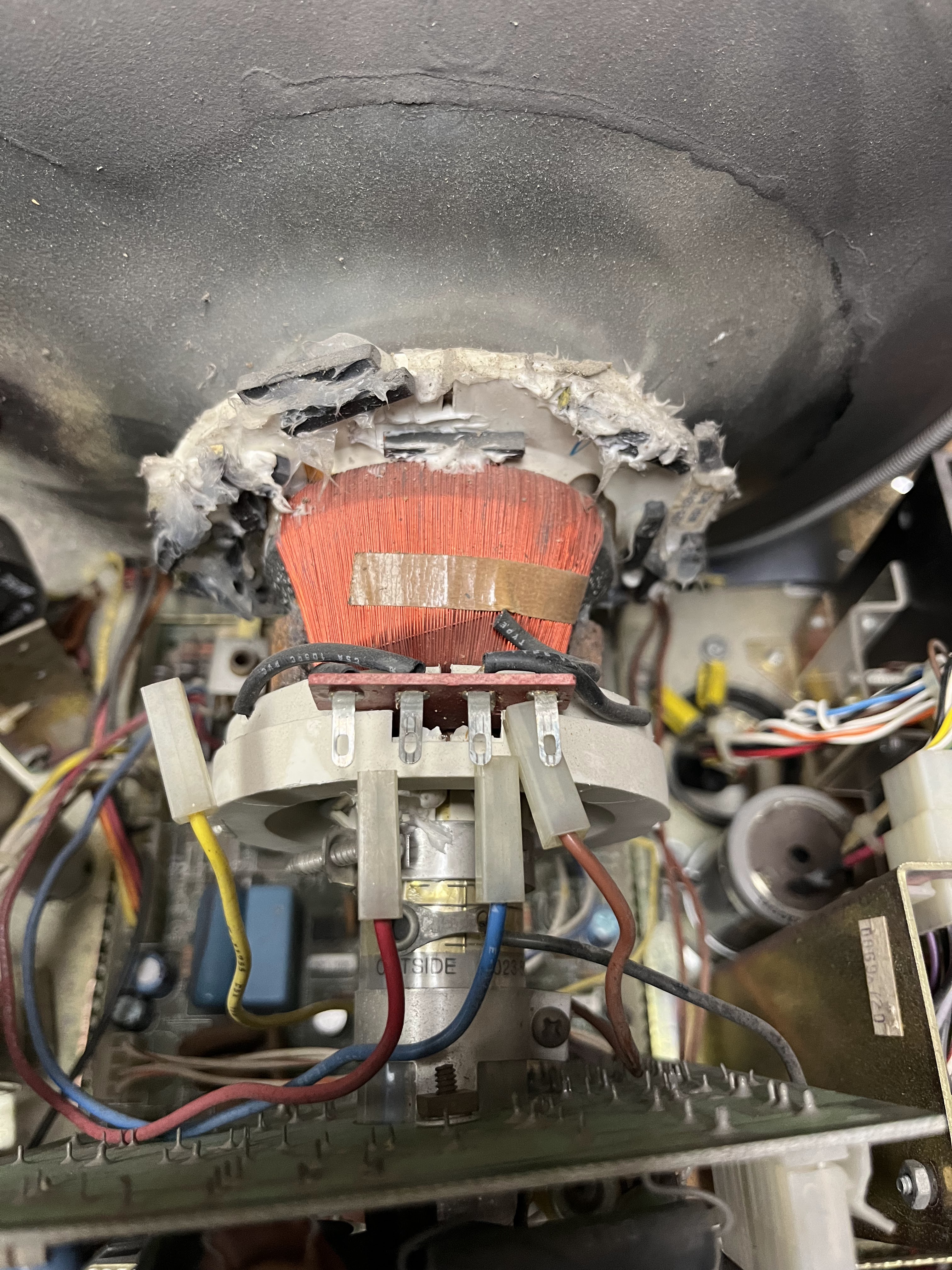
The 1100 Console's deflection yoke
At this point I'm pretty close to having the system running again, but I need to fix the issue with the console's lack of vertical deflection.  The cause is the deflection yoke: the vertical windings were corroded by the glue used to hold them in place, and went open.  Fortunately, a fellow I know rewinds transformers and the like for audio folks and he's graciously taken it on as a short project, so hopefully when that's complete I'll be able to see an actual picture on screen.

After that, I need to work on the hard drive, after which I can have all kinds of fun (it'd be neat to try to get Cedar running, for one..)  Then... I tackle the Dorado...


Other Projects

In addition to the Dolphin and the Dorado projects, I also semi-recently acquired a DEC PDP-11/60, an 11/20, most of a Honeywell DDP-416 processor, a Raytheon 704, a DEC KS10, and I will be taking a trip later this year to grab a PDP-15.  I also still have to finish restoring the PDP-11/45, reading in about 80 QIC tapes for the Three Rivers PERQ, and there's probably at least three other things I've forgotten. I guess what I'm saying is: I have a problem, this blog is a cry for help, won't someone please help me end the pain.

Until next time (probably September of 2025, by my reckoning), be excellent to each other... and PARTY ON, DUDES!


Tuesday, January 4, 2022

2021 Recap and Some Kind of 2022 Plan

Whither PDP-11/70 Updates?

You know, I'm glad you asked.  Well, not glad, but also not unhappy that you asked.  Just kind of a calm, lukewarm tapwater of feelings because you asked about this.  Actually, no one has asked about this.  I don't think anyone reads this blog, that's fine, I mostly do this because every now and then the weasels in my skull get loud enough that I need to vent the pressure, in blog form.  And also by mixing my metaphors.

Where was I?  Soon.  I'll have another PDP-11/70 entry soon.  I have plans.  Such plans.  I don't want to spoil it for you but I more or less wrapped the project up months ago and man am I bad at keeping up with blog posts.  Besides, the true hotness these days is video, so what I clearly need to do is buy a GoPro, strap it to my forehead and just start soldering stuff on camera while rambling about technology and unboxing things and just kind of fetishizing computer objects and saying things like "can you believe that the processor Steve Jobs invented for your cellphone is 1000x more powerful than this here refrigerator sized computer" and all that jazz.  It's about metrics, it's about eyeballs, it's about pretending I know what I'm talking about, it's all about the dopamine rush of Being Liked on the Internet.  Give it to me.

OK, but what about the Motorola MDP-1000?

Quiet, you.

So what are you going to write about, then?

Well as it turns out one of the reasons I didn't write much about either of the above two things is that I got distracted.  By stuff.  Other projects.  Turns out I'm easily distracted and in this grim meathook hellscape of a decade distractions are what keeps me from going out of my everloving mind.  So I thought I'd do a brief recap of the distractions from 2021, and the distractions I have planned for 2022 and beyond.  I kind of hope to write a bit about them over the next year, perhaps even with some kind of regularity.  I owe it to you, the one person who reads this blog.  Thank you for your patronage, it means a lot to us.

So without further ado, here's a rundown of interesting new acquisitions in 2021, in roughly chronological order, and some of the projects that may or may not have resulted from them.

Three Rivers PERQ 2 Workstation

You may or may not be familiar with the Three Rivers PERQ workstation, but suffice it to say it is one of the more interesting workstations to come out of the early 80s.  Designed in 1979, released to the world in 1981 and more or less forgotten today, the PERQ was a very ambitious machine: 768x1024 bitmapped graphics, with a microprogrammed bitslice processor, a megabyte of memory, 24mb local storage, ethernet, and a mouse-like pointing deivce.  All in a package that'd fit (mostly) under your desk and for a very reasonable price.  It was well ahead of its time in 1981 but unfortunately for a variety of reasons it failed to find a foothold in the market.  

This is one of the rarest PERQ systems that 3RCC actually shipped.  The PERQ 2 was an attempted refinement of the PERQ 1 workstation c. late 1982 with the intent of reducing the amount of noise the system generated.  The PERQ 1 was fairly loud, housing a 14" hard drive and a pile of fans with very little in the way of acoustic design.  Having one running under your desk made for a loud, hot workspace.  The PERQ 2 attempted to solve this by using a smaller 8" drive and enclosing everything in a ton of metal with fewer fans.  Unfortunately this had the side effect of making it difficult to service and much more prone to overheating.  And it was still pretty loud.

Not many of this system were made.  It was pretty quickly superseded by the PERQ T1 and T2 systems designed by ICL in the UK.  This particular unit was in use at Carnegie-Mellon University, apparently as a 3mbit to 10mbit Ethernet bridge, running Accent.  (The 3mbit hardware is, alas, no longer in the system.)  I'd never even seen a picture of one of these before I acquired the specimen pictured above.  It's in excellent shape (the monitor has a couple of dings that'll buff right out) and I hope to restore it to operating condition later this year.  The biggest unknown is the 8" Micropolis hard drive.  It's an uncommon drive with a nonstandard interface that's apparently prone to failure.  Good times.  Wouldn't be the first time a Micropolis drive has let me down when I needed it most.

ICL PERQ 3A Workstations

The PERQ 3A.  Well, two of 'em.


The PERQ 3A workstation was the last gasp of the PERQ line, c. 1985 or so, and never made it to market.  Rather than use a custom bitslice processor it uses a conventional 16Mhz Motorola 68020, hoping to compete with Sun et. al in the then hot UNIX workstation market. The systems pictured to the left are prototypes, and I'm hoping to get at least one of them to work.  I was able to recover most of the data from the hard drives in them and it looks like one of them may have source code for the 3B's operating system -- PNX, a UNIX System V R2 port done by ICL.

Just a few ECOs here...

DEC RF08/RS08 Fixed-Head Disc Drive

The RF08/RS08 system is an early storage device for PDP-8 systems.  A single RF08 controller could control up to four RS08 fixed-head disc drives.  Each RS08 drive contained 128 fixed heads, addressing 256KW (12-bit word size) of storage on a single fixed platter in the drive.  Thus a complete RF08 system could provide 1 megaword of storage, which was nothing to sneeze at in 1967 on a system as small as the PDP-8.  The disk assemblies are extremely fragile and very difficult to run due to an interesting design decision: when the drive is spun down, the heads rest on the platter.  This makes it all too easy for the heads to damage the surface of the drive, especially after sitting at rest for 50 years.  

The rack pictured above shows the first powerup of the controller and drive logic after restoring the power supply.  My intent is to emulate the RS08 side of things with a modern microcontroller and use the original RF08 controller with it.  I hope to make this my primary project starting early this year, it would be really cool to get it running with my PDP-8/I system.  My ultimate goal is to use it to run TSS/8 on my PDP-8/I.  The RF08 was used as primary storage and swap space for TSS/8 systems, due to its fast response time (no waiting for heads to seek!).  If I can get an emulated drive working, I may then attempt to restore an actual disk unit, but it's going to be a lift and I'm not really expecting success with it.  Just too many fiddly parts.  The two disk assemblies I have have had all their cabling cut, none of the platters are in particularly great shape and I have no idea what else is in store for me should I attempt to take it on.

RS08 Platter (note the cut ribbon cables)
RS08 heads


AMI Jukebox


OK, this isn't a computer but I always wanted a jukebox and this showed up locally for a really ridiculously reasonable price and I had to have it.  It plays 45s, it's neat, it's complete, it needs a complete overhaul but it was made in my hometown and I love it and it is mine.


Wicat 150WS Workstation

In mid July of 2021 a kind fellow out in Port Angeles offered me a huge lot of old workstation hardware -- Early Sun, SGI and Wicat systems with tons of spares and piles of documentation.  I drove out there in a rented cargo van with a friend and we loaded the van to the gills and returned with some real gems.  Wicat was one of the first companies to build a system around the Motorola 68000, and the 150WS is one of their earliest systems, c. 1982 or so.  At introduction it ran UNIX as well as Wicat's own MCS operating system.  As time went on, Wicat focused more on MCS and was moderately successful into the early 90s.

I got three incomplete 150WS systems and a box of spare parts and was able to make one reliably working system out of them.  The major issue is the multibus backplanes -- these had been sitting in a garage for a couple of decades and picked up a fair amount of corrosion that I was unable to completely eliminate in two of the systems.  It should be possible (if painful) to replace the P1/P2 connectors in the slots with new (or new-old-stock) parts but I haven't yet attempted this.  

I'm still working on cataloguing all the hardware and software that came with the systems, I've scanned a few thousand pages of documentation and I still have a few piles left to go. 

SGI IRIS 2400 Turbo Workstations


As part of the Port Angeles haul, I also acquired two SGI IRIS 2400 Turbo systems and enough spares to populate a third system.  This is a system I've been looking for for a long, long time.  Early SGI hardware is extremely uncommon and to be offered this stuff was a dream come true. 

The 2400 Turbo was introduced in 1985 and is based around the Motorola 68020.  (The earlier non-turbo system was 68010 based, as were its predecessors, the 1000-series).  It featured a geometry engine consisting of a pipeline of 12 custom VLSI processors dedicated to transforming, clipping, and scaling of 3D points, as well as a microcoded rasterization engine based around four AMD 2903 chips.  The display supported up to 32 bitplanes, used for storing pixel and z-buffer data.

Both IRIS systems I received were in fairly decent condition but hadn't been run in years.  One of the two was completely empty apart from backplane and power supply.  In December I undertook an effort to get one of the two up and running, and thanks to the help of a friend I got the system passing diagnostics and booting GL2-W3.6 just about a week ago.  I intend to write a more detailed post about this system later this year if all goes well, and I'd like to try to get the other system running as well.

Xerox 1100 ("Dolphin") and 1132 ("Dorado") Workstations

Xerox 1100 (Dolphin) on the right

Xerox 1132 (Dorado) on the left

Example Dorado board.  Note the edge fingers on both sides!

The Dorado's Base Board (front-end processor).  Note the 6502 processor, how cute.

The Dolphin and Dorado are two workstations that mere mortals shouldn't be allowed to look at, let alone possess.  Both of these were intended as personal workstations for working in the Interlisp, Smalltalk, or Mesa programming languages and both are mostly forgotten -- overshadowed by the Alto and the Star workstations.  Technically they were sold commercially as Interlisp and Smalltalk workstations -- brochures exist and they showed up in industry rags -- but most were used internally at Xerox PARC.  Only a handful of each were made.

The 1132, aka the "Dorado" or "D1" was the first successor to the Alto, and design work began on it in 1975 in the CSL (Computer Science Laboratory) at Xerox PARC.  It was intended to deal with some of the Alto's shortcomings: limited memory, relatively slow speed and lack of virtual memory.  The first prototype ("Model 0") was complete and running in 1978, and the "Model 1", which improved on the original design based on lessons learned while developing the prototype, was running in spring of 1979.  By 1983 there were around 75 Dorados in use at PARC as personal workstations for the programming staff.  An interesting writeup of the history and design of the Dorado can be found here, it's a fun read and you should check it out.

The Dorado was also available commercially as an Interlisp-D or Smalltalk-80 system, though I have no idea how many were sold -- it cannot have been many, and I suspect most went to universities and research firms.

The Dorado made up for the Alto's shortcomings, and then some.  It was based around 10K ECL technology with a microcode clock speed of 16Mhz and provided for up to 8mb of memory.  Execution was pipelined with an Instruction Fetch Unit (IFU) and under (extremely) optimal conditions could execute 1 Mesa PrincOp per microcode clock, or 16 million instructions per second.  It was blisteringly fast for the time, and absolutely insane for a computer intended as a single-user, personal workstation.  If you wanted to run Smalltalk quickly, this thing was what you needed.

Relative speed of Smalltalk-80, c. 1982, from here.


The Dorado did have a few disadvantages: the use of ECL made it extremely power hungry, which meant that it also required a lot of cooling, which in turn made it too loud (and hot) to have in your office.  Unlike the Alto, which lived under each engineer's desk at PARC, the Dorados had to be housed in air-conditioned computer rooms, with only the consoles located in programmers' offices.

The Dorado is more than likely the system that Steve Jobs and Bill Gates saw Smalltalk demonstrated on, not an Alto.


Cover of 1100 SIP Brochure
The 1100, aka the "Dolphin" or "D0" was the first system made by Xerox's System Development Department (SDD) which also made the Star.  The exact history of the Dolphin is a bit vague.  Early prototype units were in use at PARC as early 1979-1980 but were available commercially as the "1100 Scientific Information Processor" in 1982 or so. 

Like the Alto and the Dorado it's based around a custom bitsliced, microcoded, task-oriented processor, and like other machines in the "D" series it's designed to execute Mesa bytecodes efficiently (though they were popular hosts for Interlisp-D and Smalltalk-80 as well).  Like the Alto before it (and the Star after) it used standard TTL components.  It contains a 24" Shugart SA4000 disk for local storage, up to 1.5mb of memory, bitmapped display, and both 3mbit and 10mbit Ethernet interfaces for talking to the world.  (It is, in fact, the first system to use a 10mbit Ethernet interface, which had just become standardized at the time the 1100 was introduced.)

The 1100 is about the size of the Alto -- it'll fit under your desk and doesn't make too much noise.  It was faster with more memory, and was more capable than the Alto (but a bit less so than the later Star.)

The 1100 and 1132 systems I acquired this year were both used at the Language Research and Development Center at the University of Pittsburgh.  At this time I have no idea what exactly they were being used for there, but I'm hoping that some digging around may turn up more information.  I have a acquired a console that can be used by either of these systems, but it's not yet come home.  

At the moment I'm working on getting the 1100 to boot over the 3mbit Ethernet, using Ken Shirriff's 3mbit BeagleBone adapter for the hardware, and my IFS software to provide the services needed to do so.  I have it successfully pulling down microcode from the network, but diagnostics run by the microcode indicate a failure on the memory controller that I'm working on resolving.  I'm hoping to have things successfully booting by the time the console arrives, so I can use the network to back up the contents of the hard drive.

DEC TC01 DECtape Controller

I've been looking for a DECtape controller to use with my PDP-8/I for quite some time (as part of my "Get a PDP-8/I Running TSS/8" scheme) and one came up locally in trade for a different DECtape controller.  This thing has everything -- blinkenlights, Diode-Transistor Logic, and lots and lots of flipchips.  Not a single integrated circuit in the thing and it was a real joy to debug, even when it was confusing the hell out of me.  After a couple of weeks of debugging this back in November it's up and running, paired with a very nice TU55 drive I traded a rather dirty TU56 for.  I booted OS/8 from it late last year, the first time my PDP-8/I has run a real operating system in a very long time.

Now I need to find a Data Multiplexer (DM01) so that I can run both the TC01 and the RF08 at the same time.  Then I will be living the dream.

I may also have a functional DW8E soon...

Conclusion

In conclusion, computers are a land of contrasts.  I will be taking no questions at this time.


Tuesday, September 28, 2021

PDP-11/70: In Which Josh Finally Writes Some More

Ahem.  Sorry about that, seems like I forgot what I was doing here.  Where was I?

February 9: The Saga of LOAD ADDR

When we left off, the 11/70 was showing signs of life but wasn't executing instructions and, more pressingly, the "Load Addr" switch would stop working after the system warmed up for a minute or so.

Some experimentation revealed that the switch itself was still functioning (eliminating the front panel as the issue) along with most of the logic behind it:  Toggling Load Addr wouldn't load the data in the data switches into the address register, but it would happily load zero into it.  This was further verified by stepping through the microcode and verifying that the correct branch was taken when the switch was toggled.

Having confirmed that, I tried running the system using the KM-11's RC clock.  The KM-11 has three options for controlling the system's clock:  it can run normally using the 33.3333Mhz crystal on the TIG, it can single step the processor with the toggle switch, or it can run off of an RC-generated, adjustable clock, also provided by the TIG, but only used when debugging with the KM-11.  This clock is adjustable via a small trimpot on the TIG and allows running the clock slower or faster than normal, for margin testing.

With the RC clock selected and running at about 2/3 normal speed the Load Address switch functioned without issues, even after warming up for several minutes.  This would tend to indicate a marginal component that worked properly under-specced, but failed at rated speeds.

Since the issue didn't reproduce at slow speeds, stepping through the microcode to find the culprit wasn't an option.  Before bringing out the Big Guns (i.e. The Logic Analyzer) I traced through the flows diagrams to see if any obvious test points emerged.  

Looking at FLOWS 14, ADR.00 is the only possible culprit (as it's the only microinstruction in the path that modifies PCA, the internal representation of the PC register).  Since the address isn't getting loaded, either PCA <- BR (load the PC with the Bus Register) isn't functioning, or the T5 clock that triggers the former isn't being generated.

The T5 signal looked fine on the scope, so the PCA <-BR logic was the next thing to look at.  The signal that triggers this operation is generated on the DAP (DAta Paths) board below and is called DAPJ CLKPCA H.  It's generated by the combination of the TIGD T5 H (T5 clock) and RACA UPCA H, a signal generated by the microcode PROMs for instructions that need to load PCA.


Putting the scope on pin 6 of the 74S11 at E43 (i.e DAPJ CLKPCA H) showed no output at all.  The T5 clock input was clocking just fine, but the RACA UPCA H input was a flat line, indicating that the fault was elsewhere.

RACA UPCA H is generated on the RAC (ROM and Address Control) board, so the DAP board was reinstalled and the RAC board brought out on the extender for testing.  And after doing so... the problem went away!  I reinstalled the RAC board directly in the backplane and the issue remained fixed.  Despite my best efforts I couldn't get the issue to rear its ugly head again, so I considered it fixed.

This is the first instance of an intermittent backplane connection causing issues, and I suspected it wouldn't be the last.

February 10-12: Making Instructions Execute

Now that it was possible to load addresses reliably via the front panel, it was much easier to toggle in short test programs to debug instruction execution.  As you might recall from the last post, instructions wouldn't execute at all:  Hitting "Start" would immediately return to the Halt state, and the PC would not be incremented.  "Continue" behaved similarly.  

Fortunately, this behavior was traceable using the KM-11 to single-step the microcode.  Tracing through the microcode indicated that the microcode flow was aborting early and returning to the main console loop (via BRK.90) before the expected instruction fetch and PC increment at FET.10.  

Under normal circumstances, the branch to BRK.90 would only be taken if the BRQ signal was set.  BRQ (Brake ReQuest -- literally "put on the brakes, we're stopping this thing") indicates that the processor has been halted for some reason: the halt switch, power failure, an interrupt or a trap, for example, and causes a microcode jump back to the top of the main console loop, aborting the current operation.  In this case, it was short-circuiting the instruction execution before anything at all could happen.

And sure enough, probing the BRQ signal (TMCB BRQ TRUE H), on the TMC (Traps and Misc. Control) board showed that it was stuck high.  

As you can see the TMCB BRQ signals are generated based on a whole slew of inputs there on the left -- interrupt requests, traps, the whole lot -- all being OR'd together.  Tracing backward from the 74S11 at E61, the 74S04 at E55 tested fine but the 74H30 at E70 had an output value stuck at 1.65V regardless of the inputs.  This is not a valid TTL signal level for either a logical 0 or 1, stuck somewhere in no-man's land between the two.  However, the 74S04 (inverter) at E55 thought it was just high enough to count as a "1" and thus provided a nice clean logical 0 at the output on pin 8, resulting in TMCB BRQ TRUE H being stuck high.

Debugging the TMC


I replaced the 74H30 and now individual instructions were executing, in a certain sense.  Unfortunately, after each instruction, the PC contained garbage rather than the next address.  

For example, executing a simple HALT instruction at address 1000 should increment the PC to 1002 and then halt the processor.  What I was seeing was a halt with 3602 in the PC instead.  Sometimes this value varied, randomly.

This one was puzzling and it took me a bit of poking around to figure out what was going on.  The PC register (also referred to as R7) in the PDP-11 is actually split into two separate registers within the PDP-11 hardware: PCA and PCB.  These are modified during instruction execution and are used to store intermediate values for various address calculations.  As described in the introduction to Chapter 2 of the 11/70 Processor Manual:

The data paths diagram below outlines how data gets around the processor, as controlled by the microcode.  PCA and PCB are in the middle near the top and you can see that after exiting the ALU, a calculated address goes to PCA and then through to PCB; PCB is used as the source value for operations involving the PC in many places:

There will be a quiz later.

So my suspicion immediately fell upon the poor PCB register, and my initial thought was that the transfer from PCA to PCB wasn't working properly and was picking some bits in the process.  The logic for these two registers is below (well, for bits 6-15, anyway, 0-5 are on another sheet):


PCA and PCB are built out of two sets of three 74S174 hex flip-flops.  The controls to this consist of a "Clear" (which clears the register) and a "Clock", which loads the data present on the data lines into the flip-flops, thus storing a new value.  As you can see, PCA is directly connected to PCB, and a transfer from A to B will occur when DAPJ CLKPCB H goes high, clocking the data from the output of A into B at the request of the microcode.  The output of B connects to a multitude of other places in the processor.  (The input of A comes from the ALU which itself takes inputs from a number of potential sources -- see the earlier paths diagram to see them all.)

If DAPJ CLKPCB H wasn't getting signaled then PCB wouldn't get updated at all from PCA and apart from that there's no other way for data to get into PCB.  But clearly PCB was getting clocked, since the value in PCB was getting updated (just incorrectly).  Was it possible that the outputs from PCA were incorrect?  Unfortunately no -- probing the outputs of PCA showed the correct value.

Hmm.

After some more experimentation, I noticed that the corrupted data was only present in bits 6 through 11 of the final PC value.  Executing a HALT at address 100000 (which should halt at 100002) instead halted at 102602 (or thereabouts -- as before the value was slightly random).  A HALT executed from 0 halted at 2602, and so on. That corresponds nicely to the arrangements of the three 74S174's comprising PCB, each containing 6 bits.  The "middle" 6 bits of PCB were in the '174 at H47 on the DAP board.  I replaced this with a spare and afterwards, single-stepping instructions worked properly! 


I tried a variety of different instructions and single-stepping through them appeared to work correctly.  However, at full speed a simple loop -- like a "BR .-1" (000777) -- would not loop for very long.  After running for a few milliseconds at most it would somehow jump past the the branch instruction and end up at the next address.  Other short programs behaved similarly, running for a short time before ending up off in the weeds.

I spent the next few days poking and prodding, but the details of this must wait for the next EXCITING INSTALLMENT of this saga.  Which hopefully I'll get written up before the heat death of the universe but we'll just have to see.  Until then, keep on keepin' on.

Saturday, April 24, 2021

PDP-11/70: Even More Stuff

January 2021: Debugging Commences

In my last post I left off my tale of PDP-11/70 restoration in late January, having just powered up the rebuilt supplies after reinstalling them in the chassis.  The next step was to reinstall the processor, cache, and memory and see what happens:

(not quite) The First Power-up with Stuff Installed

The answer is: not much.  The processor was almost entirely unresponsive: it powered up with the RUN and MASTER lights on and wasn't responding to most input from the front panel.  Toggling the "Halt" switch and hitting "Start" caused the RUN light to go out, but that's the only response I got from the console.

Enter the KM11-A:

How does one debug a processor as complex as the 11/70's?  These days, advanced diagnostic tools like Logic Analyzers and digital storage oscilloscopes are commonplace, but in 1974 they weren't really an option.  DEC's solution to this was the KM11-A "Maintenance Set", a pair of boards with an array of lights and four switches.  The lights were used to monitor device state, and the switches controlled the behavior of the device and allowed for single-stepping processors.  The KM11 could be used to debug a variety of DEC hardware -- various PDP-11 processors and a few different peripherals and device controllers.  My KM11-A is a reproduction, which I built over a decade ago to debug my PDP-11/40, since then I've also used it to repair my PDP-11/05.  And now, it's time for the KM11 to work its magic again.

With the KM11 boardset installed  (you can see it sticking out from the left-hand side in the above picture) I was able to step the processor through micro-instruction execution.  A toggle switch on the KM11 clocks the processor, and the DATA lights on the front panel show the microcode address in the right 8 bits (with the selector knob turned to "uADDRS FPP/CPU).  (In the above picture it's showing address 200 octal).  The PDP-11/70's KB11-C processor is microcoded, using an array of small, high-speed bipolar PROMs to store 256 64-bit microcode words.  These 256 words are interpreted by the hardware to implement the PDP-11 instruction set, address memory and the Unibus, and to interface the processor to the front panel.
 
The KB11-C Engineering Drawings contain 14 pages of "flow diagrams" which detail precisely how the microcode executes.  The "KB11-C Processor Manual" (EK-KB11C-TM-001) provides 376 pages explaining exactly how the hardware works.  A typical flow diagram looks like:
Feel Flows
This is FLOWS 14, which diagrams the Console (front panel) portion of the microcode.  Top-center, you can see a starting bubble labeled "CON.00" which marks the start of the console portion of the microcode.  The box below it represents a single microinstruction, and details the operation of this microinstruction in each of the processor instruction cycle's "T-states."  The arrows coming out of this box indicate branches to other microinstructions, depending on the state of the hardware at the time of the instruction execution.  Branches may also lead to other flows (indicated by diamonds). 

Use of the KM11 indicated that the processor was definitely executing microinstructions, and seemed to be following the flow diagrams in the engineering drawings.  This is excellent -- it indicates that a lot of the hardware is functional.
 
Curiously, left to its own devices the processor didn't seem to be executing microinstructions at all and was stuck at micro-address 200 octal.  This is "ZAP.00" in the flow diagrams and is where the processor starts at power up or after a reset.

In the troubleshooting section of the 11/70 service docs (diagram on p. 5-16) it states:
IF LOAD ADRS DOES NOT WORK AND:
- RUN, MASTER & ALL DATA INDICATORS ARE ON
- uADRS = 200 (ZAP)
THEN MEMORY HAS LOST POWER
Which seems to adequately describe the symptoms I was seeing -- there is power-fail hardware in the processor that forces the microcode address to 200 in the event that power is lost, but the AC and DC LO signals (which are what the power supply uses to tell the processor of such a failure) were all fine (after checking again, just to be sure).   Also if this was the case I wouldn't expect that the KM11 would be able to step the processor at all -- the power fail hardware should force the processor's microcode address to 200 at all times until the power failure is resolved.

Probing the processor clock signal on the backplane with an oscilloscope revealed no clock signal at all, just a flat line.  The clock signal is provided from one of three sources on the "TIG" (Timing Generator) board:  Normally it comes from a 33.3333Mhz clock crystal.  While debugging with the KM11, it can come either from the MAINT STPR switch on the KM11, or from a special diagnostic RC clock network on the TIG board (this latter can be adjusted to a wide range of frequencies for margin testing.)  This lack of a clock signal was definitely an important clue.

Another oddity was revealed after a closer look at the service docs: In Chapter 4 of the Processor Manual, Section 4.1.3 it states:

"The third source of timing [the other two being the crystal clock and a diagnostic R/C network] is the manually-operated, single-step MAINT STPR switch S4, located on the maintenance card.  This switch is only enabled when maintenance card switches S2 and S3 are both set to 1."

Section 4.2.3 confirms this:

"The maintenance card S2 and S1 switches are both set to 1 to allow single timing pulses to be generated by MAINT STPR switch S4.... Removing the S2 or S1 input conditions the MS EN flip-flop to be cleared."

What was interesting about the above is that on my system, switch S4 (MAINT STPR) stepped the processor with switches S1 and S2 set to any configuration.  This being the case, I wondered if the logic that selects the clock source was faulty, and was always selecting the MAINT STPR input.
 
Well, only one way to be sure, and this would require getting the TIG board out on an extender for some extensive probing.  In doing so, I found that no clock signal was being generated by the 33.3333Mhz crystal at all; in fact while probing it one of the legs to the crystal fell right off.  This is usually a sign of a faulty component.

So I placed an order on Digi-Key for a replacement.

But then I got impatient and remembered that the rusty burned-out hulk of a PDP-11/45 I picked up along with the 11/70 was in the garage, and the 11/45 also has a TIG board, very similar to the one in the 11/70, and also using a 33.3333Mhz crystal.  
 
A short while later, the 11/70s TIG had a new, stolen, clock crystal:
Where'd you get that shiny new crystal?

And after reinstalling the TIG back in the backplane and powering up:


It's alive!  A bit.  With a working clock, the processor was able to respond to the front panel and I was able to load addresses and examine and deposit into memory.  However, instructions would not execute -- loading an address and hitting "Start" on the front panel had no effect.  More pressing: after the system warmed up for a minute or two, the "Load Address" switch on the front panel would stop working properly, and would always load "0" rather than what was in the front panel switches.
 
Still, good progress for just a few evenings of research and debugging (and conversing with people on cctalk for advice.)  Over the next few days I started in on investigating these issues... which I'll talk about in my next exciting installment.  Until then... go find something else to read.


Saturday, April 17, 2021

PDP-11/70 Repair: Part One

Looks like a few months have passed since my last post, as seems to be typical.

Never you mind, let's just ask the question: How'd that whole "Restore a rusty soot-covered PDP-11/70" thing turn out?  Well, I don't want to spoil anything.  Let's pick up where we left off.


November 2020:Make it Look Good

Looking good!

Well, first I installed the replacement front panel assembly.  That'll get you 90% of the way there, as anyone who restores old computers can tell you.

December 2020, January 2021: Cleaning, Capacitor Reforming, and Fan Replacement

Despite a pretty new face, the computer was still extremely dirty.  When I first brought the system home I'd given the rusty parts a rough sanding to get rid of the grit and loose paint, but the inside of the chassis was still amazingly filthy. 

Dirty Little Fingers

The boards themselves cleaned up quite well: they were all covered in a fine grit of soot and who knows what else, but soaking them in warm soapy water for 10-15 minutes then scrubbing with an old toothbrush eliminated most of the detritus.  After drying in front of a box fan, the gold fingers were cleaned up with liberal use of Scotch Brite(tm) cleaning pads.  

None of the 17 boards that comprise the Processor, Cache, and Memory of the system appeared to be seriously damaged.  That's good!


My next major concern was whether the backplane itself was hiding some corrosion -- corroded pins make poor contact with the boards and might never work reliably.  And these pins aren't exactly trivial to replace -- while it might theoretically be possible to undo the wire wrap to a bad pin, desolder it from the backplane assembly PCB and remove it... no, you know what: it's impossible for all intents and purposes.  If you have a dead pin on a backplane like this, the backplane (and it follows, the computer) is toast.

This weighed fairly heavily on my mind, as soot and moisture could easily have destroyed this computer.


Empty backplane, mostly.
With the boards removed for cleaning the chassis was now empty, with the backplane exposed for easy (if extremely slow and somewhat painful) cleaning. There are 44 slots in the KB11-C backplane, each of which is divided into 6 sections, designated A-F.  Each one of these sections needed to be cleaned.  A strategy I've used in the past is to fold a thin piece of cardboard over a credit card; this jerry-rigged assembly can be dipped in 99% isopropyl alcohol and then used to clean the slot by inserting it and removing it a few times.  Accumulated dirt and light corrosion will be pulled off leaving the slot at least slightly cleaner than it started off.  For good measure, before starting on each slot, I gave it a good dose of contact cleaner to help loosen things up.

Repeat this for all 6 sections of all 44 slots.  I did this over the course of about three weeks, a few slots every night to prevent my fingers from falling off.  Most of the slots were already pretty clean, but on a few the cleaning card came out quite dirty and required a few extra passes.  The last few slots toward the rear of the chassis took the most time to clean.

Had I to do this again, I might have tried removing the entire backplane from the chassis and rinsing it out with water or isopropyl first, but I got pretty good results with this approach.

Reforming Capacitors

In the midst of the above cleaning process, I started in on the power supplies.

The PDP-11/70 gets its power from two H7420a power supplies.  Each H7420 is a large bulky unit with an extremely heavy transformer up front; this transformer provides 30VAC to up to five modular power supply units which take the AC and provide regulated DC.  Different modules provide different voltages; the H745, for example, provides -15V at 10A; the H744 provides +5V at 25A, the 754 gives you +20V and -5V.

Depending on what system you have and what options it has fitted, the H7420 might have a variety of these modules installed.  For the PDP-11/70 system I have, it's entirely H744s -- seven of them, providing a whole lot of +5.  The H7420 itself provides + or -15VDC, as well as 8V and the ACLO and DCLO signals used to let the computer know if it's about to lose power.

A really dirty H744, prior to cleaning.

Over the course of a month, each of the H744s was removed, disassembled and cleaned.  The capacitors were removed and reformed.  Normally, I like to replace capacitors, rather than reforming just for the sake of reliability and peace of mind.  However, I thought I'd give reforming a try this time around, mostly due to cost considerations:  Each H744 contains three large capacitors, and with seven of them to restore (plus two extra for spares that I happened to have lying about), it was looking like I'd be investing about $750 to replace them all.

I won't go into details on capacitor reforming here -- it's well documented all over on the 'net (David Gesswein has a nice write-up here) and it's not all that exciting.  The upshot of my reforming experience was that of the 28 capacitors in the supplies, four of them ended up being marginal, and two were completely dead.  Not too shabby.  

Testing of the supplies (and the capacitors) was done using an electronic load that I bought for the occasion.  It's a lot more convenient than using banks of resistors, and it looks cool too:

Burning in an H744 (middle) on the bench.  Electronic load on the left, H7420 on right.

The electronic load gives me the ability to vary the load while testing, starting with a small amount of load for initial smoke testing, then ramping it up to really soak test the thing.  I let them run for a couple of hours each.  While this is going on, the output of the supply is monitored on an oscilloscope, to check that ripple is within tolerances (about 200mV, max). This is also a good time to do an initial adjustment of the voltage level (each H744 has a small potentiometer exposed on the front that is used for this purpose).

Of the 9 H744s, all but one tested out fine and required no additional repairs.  The one that failed would occasionally make an interesting short squeaking noise, with an associated drop in voltage.  I put that one back on the shelf for a future investigation (which as of this time has not yet occurred).

Fan Replacement

I have neglected to mention the state of the fans in this system: they were bad.  Very bad.  There are 18 fans in the PDP-11/70: 8 in the two H7420s, and 10 in the processor chassis.  Of these 18 fans, only three actually spun freely and even those sounded pretty bad when doing so.

OBEY THE PAPST FAN

I opted to replace these entirely.  While some of them were designed to be disassembled and cleaned, they were all rusty to the point where I just did not want to bother.  I found a decent supply of Papst fans on eBay for a reasonable price.  These are nice fans, well built with metal blades rather than the more common plastic ones.  Heavy.  Elegant.  Subtle.  Hungarian.  I like them.  

I installed 8 of them in the H7420s and reinstalled six of the H744s (and one H7441 that snuck in there while I wasn't looking.  See if you can find it, it's really exciting).

The supplies: all cleaned up and put back together!

At this point, all the wiring was double-checked, both for continuity and also for shorts and breaks in the insulation.  Everything checked out OK, so I fired the system up with an empty processor chassis, while holding my breath:

Hey, not bad.  No smoke or fire or bad smells, and the front panel lit up (all the lights are on by default since it's disconnected from the logic that normally drives it).  All voltages at the backplane were tested, per the service manual:

This is actually kind of a pain in the neck because you're finding tiny pins in a rat's nest of


The wire-wrap side of the 11/70 backplane: Where's Waldo?

and trying not to accidently brush against another pin while doing so.  I used a set of small jumper wires that clip over the ends of the wire-wrap pins to help keep things isolated.  Even so it was kind of nerve-wracking.  Long story short: all voltages were present in the right places on the backplane, and the ACLO and DCLO signals were both high, as they should be.

Conclusion:

As January drew to a close, I had gotten the PDP-11/70 to a point where it was clean and safely powering up.  What would the following months bring?  STAY TUNED TO FIND OUT!