As mentioned in my last post, the LMI Lambda I acquired spent most of the last two decades in a garage somewhere in Pennsylvania. It wasn’t a climate-controlled garage. It wasn’t a leak-proof or a rodent-proof garage. The door to said garage wouldn’t even close all the way. So this machine was in rough condition when I picked it up. The first thing I did before bringing it in the house was to clean it out, thoroughly.
 |
| The Lambda, just outside the garage. |
Unfortunately I neglected to take too many “before” photos (at the time I hadn’t yet considered documenting this whole process) but they’d only really reveal a cabinet covered in a thin layer of grit and grime.
The outside and inside walls of the cabinet were cleaned off with some Simple Green and some elbow grease, and while this was underway I inspected the interior for rodent-related damage.
 |
| The Lambda after cleaning, sitting in its new home in my basement. Still kind of rusty, but smelling less musty. |
Fortunately, apart from the hole in the door near the top (which is hard for small animals to reach) the Lambda’s cabinet is free of any holes large enough for a mouse to squeeze into and no damage was observed. This is good: mice love to chew up wires, and their urine and droppings can eat the traces off of printed circuit boards and corrode the legs on ICs and other components. While a lot of this sort of damage can eventually be repaired, it’s difficult and messy (and smelly) work to deal with.
Removal of Batteries
After a thorough wash-down of the cabinet, things were smelling better so I had a good look at the card cage and backplane. Daniel Seagraves alerted me to the fact that the SDU (System Diagnostic Unit) contains a soldered-on nickel-cadmium battery, and that’s where I started my inspection.Anyone who’s worked on any of a variety of old computers knows that batteries are bad news. Tiny cells soldered to motherboards have been the death of many a PC, Amiga and VAXStation (and they’re not kind to arcade games either.) Over time, the batteries leak or outgas — and what comes out of them eats away at circuit boards and dissolves traces. So as I pulled the SDU out I kept my fingers crossed that the damage would be minimal — the SDU is one board I don’t have spares for. And as luck would have it, even though this thing had been sitting in a rather unforgiving environment for a long time, the battery hadn’t leaked at all:
 |
| Intact NiCad battery on the SDU. Got very lucky here. |
Whew. I got out a pair of wirecutters and immediately removed it from the board. I’m not taking any chances, and this battery will need to be replaced anyway. The rest of the SDU was in decent shape — some rust on some IC legs, and one rather rusty looking clock crystal but overall not too shabby.
Inspecting the Card Cage
When inspecting a cardcage like this, generally it’s important to make sure that everything’s in its right place: In addition to making sure that nothing’s missing, some slots may have designated purposes (where having the wrong board in the wrong slot can cause catastrophic damage) and some busses don’t like having empty slots in the wrong places. (Some backplanes don’t even have the concept of a bus at all, and each slot is hard-wired for a specific board.)
 |
| The Lambda’s cardcage as-received, still sitting on the loading dock. |
Additionally, when inspecting a cardcage in a system that’s been in an unfriendly environment it’s a good idea to carefully inspect everything for damage or foreign matter up front so you know what you’re going to be up against. It’s also a good time to do minor cleanup of corroded pins on chips that are socketed.
This is also a good time to start collecting as much information and documentation about the system as possible — this will be required in order to assess what’s missing and what goes where, and it will be essential if repairs need to be made. Bitsavers is always good place to start.
First thing’s first, let’s see what we have in the system. The Field Service Manual is a good reference to have handy while doing this, although it’s slightly outdated in some areas. The backplane is divided into sections, and slots are numbered from right to left, starting at zero. The first 8 slots are NuBus slots with a processor interconnect for the Lambda CPUs (there are two sets of four boards) and these slots are specifically designated for these processor boards. Slots 8-14 are general-purpose NuBus slots, slot 15 is for the SDU and the remaining slots are Multibus slots for peripheral controllers (Disk, Tape, and Ethernet typically). Here’s a handy table showing what’s where in my system:
| Slot | Board |
| 0 | RG (CPU 0): “ReGisters Board” |
| 1 | CM (CPU 0): “Control Memory” |
| 2 | MI (CPU 0): “Memory Interface” |
| 3 | DP (CPU 0): “Data Paths” |
| 4 | RG (CPU 1): (as above) |
| 5 | CM (CPU 1) |
| 6 | MI (CPU 1) |
| 7 | DP (CPU 1) |
| 8 | VCMEM (0): High-resolution terminal (keyboard, mouse, display) interface for CPU 0 |
| 9 | 4MB Memory: Memory for the Lisp processors |
| 10 | VCMEM (1): High-resolution terminal (keyboard, mouse, display) interface for CPU 1 |
| 11 | CPU: 68010 processor for UNIX |
| 12 | 16MB Memory: Memory for the Lisp processors |
| 13 | Empty |
| 14 | Empty |
| 15 | SDU: System Diagnostic Unit |
| 16 | Disk: Multibus SMD Disk Controller |
| 17 | Tape: Multibus Pertec Tape Controller |
| 18 | Empty |
| 19 | Empty |
| 20 | Memory: TI-Manufactured 4MB Board |
The RG, CM, MI, and DP boards together contain the logic for the Lambda’s Lisp processor, one specially designed to run Lisp code efficiently.
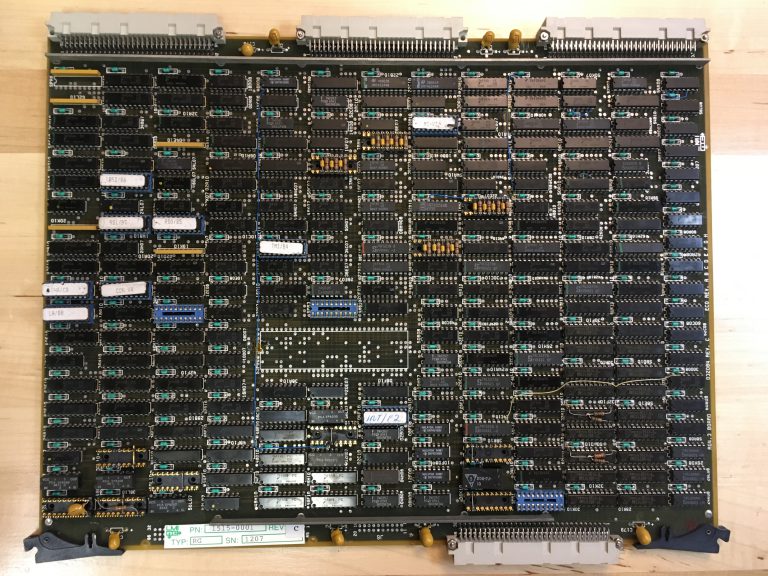 |
| Lambda CPU: RG “Registers” board |
This system is outfitted with two sets of these boards. This was a way to make the system more cost (and space) effective: A single Lambda could run two processors and two consoles (and thus service two simultaneous users) while sharing a single disk. Since Lisp Machines were typically single-user machines, reducing the overall cost and footprint in this way would make the LMI more attractive to buyers concerned about investment in very expensive computers. (Symbolics did something similar with their 3653 workstation: it contained three 3650 Lisp CPUs in a single chassis.)
 |
| Lambda CPU: MI “Memory Interface” board. |
The logic in the Lambda is built entirely from 7400-series TTL (Transistor-Transistor Logic) parts along with a few PALs (Programmable Array Logic) and EPROMs (Erasable-Programmable Read-Only Memory). The most complicated IC involved is the 74181 ALU used on the Data Paths board. The 74181 was a 4-bit ALU used in many processors of the time, though it was a bit outdated by the time of the Lambda (The Xerox Alto used them way back in 1973, for example).
 |
| Lambda CPU: DP “Data Paths” board: note the 3×3 array of 74S181 ALU chips. |
That’s good news — TTL, PAL and EPROM parts are still readily available so they can be replaced if they fail. The trick, of course, is being able to debug the hardware to the point where the bad chips can be accurately identified. At the moment, circuit schematics are not available so this will likely be a challenge.
 |
| Lambda CPU: CM “Control Memory” board |
 |
| The Motorola 68010-based UNIX CPU Board, for when you want to contaminate the beauty of your Lisp Machine with UNIX. |
The VCMEM boards each drive a single high-resolution terminal — a black and white monitor into which a keyboard and mouse plug in, connected to the Lambda by a very long cable. (The terminals typically lived far away from the Lambda itself since no one would want to work very close to a machine this loud.) I got two consoles with the machine, but only one keyboard and mouse, alas.
 |
| VCMEM board — framebuffer memory and display, keyboard, and mouse controller |
 |
| 16MB of memory |
The memory boards provide memory for the Lisp processors to use. Each processor can address up to 16MB of memory.
 |
| System Diagnostic Unit |
The SDU sits in the middle of the cardcage and acts as a middle-man, so to speak: it negotiates communication between the NuBus boards on its right from the Multibus boards on its left. Additionally, it is responsible for booting the system and can be used to run diagnostics, to format drives, and to reinstall the operating system from tape. It is based around the Intel 8088 CPU.
 |
| Multibus Interphase SMD 2181 Drive Controller, in carrier. |
The Multibus controllers sit in special carriers that adapt the boards to the form-factor that the Lambda’s card cage uses. The disk, tape, and ethernet controllers were off-the-shelf parts made by other manfacturers: 3Com for the Ethernet controller, Ciprico for the Tape controller, and Interphase for the Disk controller.
From the looks of things, everything is in the right slot, except for that TI Memory board in slot 20. That’s a Multibus slot and the Lisp memory boards won’t work there at all (and in fact could end up getting damaged if installed there when power is applied). Someone likely put it there to keep the board safe while in storage or in transit. I removed that board and put it in a static-proof bag for safekeeping.
 |
| The misplaced Texas Instruments-manufactured memory board, easily distinguishable by its use of surface-mount rather than through-hole parts. |
Board Inspection and Cleaning
While going through the card cage I took every board out for inspection and cleaning. Things to look for are severe amounts of dirt, dust, rust or corrosion, physically broken or burned components, damaged circuit board traces, bent pins, and other things that don’t belong on a circuit board.Socketed chips are good to look at closely: the sockets and the pins on the ICs are more prone to corrosion in my experience (not entirely sure why — some of this is due to being more exposed to the elements than soldered-in chips, moisture may linger in the sockets for a longer time than elsewhere; it may also be partially due to reactions between the different metals used in the sockets and the IC pins). On these boards it was not at all uncommon to find chips like this:
 |
| Fairly corroded legs on an Intel 8089 I/o Coprocessor |
Light oxidation manifests as a dull grey patina on IC legs and socket connectors; corrosion as more obvious orange or brown rust or green verdigris. Any of these will cause poor connection with the sockets and must be eliminated. Oxidation and corrosion can usually be removed with some fine-grit sandpaper or gentle scraping with a sharp X-Acto knife blade. Sometimes such cleaning will reveal legs that have corroded away so much that they fall off — which is always disappointing to find. This fortunately has not happened to any of the ICs in the Lambda so far.
Occasionally you run across something like this:
 |
| IC with a bent leg found as-is in a socket! |
This is more common than you might think — the pin got bent over when placed in the socket when the board was manufactured, but still made good contact with the top of the socket pin so the fault was never discovered. Over time, this can cause intermittent failures. Luckily it’s pretty easy to bend these back without breaking them.
And then sometimes you find something completely inexplicable:
 |
| How’d that screw get there? |
I have no idea how or when this happened, but that screw was very firmly wedged in-between those two ICs. Given that the boards are vertically oriented in the chassis, it seems really unlikely that a screw fell in the top and managed to get stuck in there. Very strange. Also not good for operational integrity. Note also the grey oxidized pins on the blue socket in the lower right of that picture. When new, those were shiny and chrome. Luckily that’s a spare socket and is unused.
Inspecting the Rear Chassis
The logic boards plug into the front of the chassis. Around back, there’s another set of connectors which small “paddle cards”plug into, breaking out signals into cables that connect to peripherals and run to bulkhead connectors like these: |
| The back of the CPU card cage. Some light pitting on the aluminum of the rear panel. |
That rear panel hinges outward and reveals the rear side of the Lambda’s backplane:
 |
| Behind the rear panel |
You can see how the backplane is segmented here: On the top running from right to left you have the NuBus portion, which ends on the left with the NuBus Terminator paddle card. (There is a similar terminator on the right side as well). On the lower-left you can see two sets of four slot backplanes for the CPU interconnects. To the right of those are the paddle cards for the VCMEM slots: These bring out the connections for the high-resolution terminals, which are cabled to DB-25 connectors on the bulkhead panels. Further to the right you can just make out the SDU paddle card. Everything to the right of the SDU slot is Multibus — the middle section of these slots carry the Multibus signals, while the top and bottom sections carry device-specific signals for disk, tape, and ethernet cabling.
The important thing to check here is that all the paddle cards are present, in the right places, and are in decent shape. This appears to be the case. All the cabling looks to be intact as well. Good news all around.
No comments:
Post a Comment