Tuesday, June 16, 2020

At Home With Josh Part 4: High-Resolution Terminal Restoration

In my previous installment I tested the Lambda’s fans and the power supply and powered things up for the first time. A few of the fans were non-functional even after cleaning and lubricating and so an eBay order was placed. While waiting for those fans to arrive, I started taking a look at the Lambda’s monitor, referred to in the documentation variously as “High-Resolution Terminals” or “High-Resolution Monitors.” Whatever they’re called, they were in need of a bit of sprucing up:
LMI Lambda monitors, mid-cleaning

If you look closely you can see the
scarring on the picture tube’s face.

I cleaned the exterior with a bit of Simple Green and some liberally applied Magic Eraser to get some of the grungier parts off. Exposure to the elements had left some interesting etchings on the anti-glare coating on the CRT; I’m not sure if they ate it away or if they just deposited a thin layer of something on the surface– either way light scrubbing with the Magic Eraser either removed the deposits or removed the rest of the anti-glare coating to match, it’s difficult to say. Eventually the external dirt and grime were removed and the monitors looked much better.
Shiny Happy Monitor

Close-up of CRT cataracts

One of the two monitors has a CRT with “cataracts” (also referred to as “CRT Rot”) in the corners. This is a problem that plagues older televisions and monitors and is caused by degradation of the thin PVA glue layer between the front of the CRT glass and the implosion-protection lens. Over time, the PVA breaks down causing small spots to appear. The cataracts here are relatively minor; on an ADM-3A terminal I recently repaired the PVA breakdown was so extreme it had started leaking out onto the circuit boards and was an absolute bear to clean up (fortunately it’s organic so it washes off with water, but not without a fight.)

On some CRTs this can be repaired, typically by carefully separating the implosion lens from the rest of the CRT, cleaning all the PVA residue and reassembling. (Here’s an interesting write-up of one such process for old TV picture tubes.) On the Lambda’s CRTs, this is made much more difficult — there is a metal band around the tube with a “lip” that extends around the front of the tube, helping to hold the whole assembly in place. This band is glued in place with a potting compound making removal of this band extremely difficult; and due to the lip the implosion lens cannot be removed without removing this band. Fortunately the cataracts on this tube are not bad enough to warrant attempting to do this — I’m happy to put up with it — and the other monitor’s tube is free of cataracts, so far.

Inspecting the Internals

Much like with the rest of the Lambda system, we have to give the internals a thorough inspection. One of these monitors was left on top of the Lambda in the garage; the other (the one with the cataracts) was on the floor near the door and was exposed a slightly more harsh environment as a result. However, they both cleaned up very nicely on the outside so my expectation was that internally they’d be similar as well.
The interior of the monitor with the back covers removed.

Looking at the interior from the rear (as in the above photos) reveals a relatively clean monitor — though you can see some obvious rust in places like the ground strap going across the bell of the picture tube. The interior of the other monitor is very similar in terms of condition. On the left side is the monitor’s power supply, on the right is the deflection board which scans the CRT’s electron beam across the screen to form a raster, and in the middle is the “neck board”, so called because it plugs into the neck of the CRT. It supplies power to the CRT’s heaters and takes the incoming video signal from the Lambda and feeds it to the tube appropriately.

Safety First, People:

It’s important to note at this time that safety is important when working on CRTs: they tend to make use of extremely high voltages (5-10KV in monochrome tubes, up to 25KV in color sets) and you can get zapped if you’re not careful. Picture tubes can build up a charge even while sitting unplugged and unused; so even though this tube hasn’t been powered up in a couple of decades it still has the potential to bite. Discharging of the tube before working on it is a good idea, as is working with one hand behind your back (to avoid causing current flow across your heart, should you grab ground with one hand and 20KV with the other, inadvertently.)

The CRT envelope is made of glass and contains a powerful vacuum; if the glass breaks the tube can potentially implode — sending glass shards everywhere. While modern tubes (like the ones in the Lambda) have implosion protection measures in place, it never hurts to be careful around large tubes like this: watch your hands, watch your tools and make sure they don’t strike the neck of the tube where the glass is thinnest and the most likely to take damage.

The Inspection Continues:

Looking closer at the power supply you can get a better idea of the cleanup necessary here — everything is covered in a layer of dirt and shingle detritus from when the garage’s roof was replaced. Just as with the Lambda’s chassis and power supplies, I’m looking for out-of-place things and broken or damaged components. All three of these boards contain socketed chips, so checking the sockets and the ICs in them for corrosion is important. I’m also keeping my eyes open for damaged capacitors. Monitors can be hard on capacitors, especially high-resolution monitors like this one. Monitors don’t typically have fans so they tend to run hot, and heat leads to shorter lifespans of internal components.

And sure enough I found my first victims on the power supply board.
RIFA film capacitors, top view.

Exploded RIFA, from the side.
These are film capacitors, used as AC line-filters in the power supply. Or at least they were film capacitors — as you can see the casings have cracked and split and have turned a deep brown in places (they’re normally golden-yellow colored). These were manufactured by RIFA, and are absolutely notorious for failing in this way, and when they do fail they emit an unforgettable odor, though not an entirely bad one (we’ll get to those smells later). Kinda like burning paper. Which is not a coincidence because these are made of metallized paper. As they age, moisture seeps in and eventually causes a short-circuit resulting in smoke, but not usually fire. (There was this one time at the museum when one of these died in action and set off the smoke detectors and the fire department came. That was a fun day…)

Even if they haven’t already clearly failed as these have, they should be replaced as a matter of course, because they will fail if you don’t. Probably within the first thirty minutes of being powered up.
Original RIFA next to its brand-new replacement.


Moving along onto the deflection board: There are a few socketed chips, and the sockets don’t look so hot. These sockets have deeply recessed pins and my suspicion is that as a result they hold onto moisture longer, increasing the chances of corrosion. As you can see in the picture below, some of the pins show the original gold-plating, while others are green or grey. It’s likely that these sockets will provide poor contact with the IC, so I replaced it with a spare I had on-hand, a nice turned-pin socket from Mill-Max:

Bad IC socket: Before
Bad IC socket: After


On this same board I found the first instance in this restoration of a visibly-bad electrolytic capacitor:
That ain’t good…

The discovery and removal
of one bad electrolytic capacitor


That capacitor is supposed to be a uniform silver in color. It is browned and blackened likely due to heat while in operation due to its proximity to that transformer, and it might have been a slightly under-specced part as well. Instant candidate for replacement, no questions asked.

On the neck board we find another kind of capacitor that can often cause issues; look closely at the four blue raindrop-shaped components in the below picture:

One of these things is not like the others.

Well, they’re all supposed to be blue, but the second one from the left is black and sure enough it’s a dead short, rather than a capacitor. These are tantalum capacitors and they have a tendency to explode in a tiny little fireball when they go bad — and they can scorch other components when they do so. And the smell they make is decidedly unpleasant. Given the state of the black one it seemed prudent to replace all four just to be on the safe side. Takes a long time to get that odor out of an already stuffy basement, I’m not taking any chances.

There is one further board in these monitors, called the “headboard” — it lives in the monitor stand and breaks out the signals on the cable from the Lambda into keyboard, mouse, and video. It also includes a tiny speaker and three controls for brightness, contrast, and volume:

Ugh. Just, ugh.

The one in the monitor that had been sitting on top of the Lambda was just a bit dusty, but the one that’d been on the floor… yow. Some serious insect activity in here over the years, and everything was pretty well covered in… insect stuff. I took the board out of the housing and scrubbed the base-plate down in the utility sink. I went over the PCB with a soapy toothbrush and Q-Tips to get as much gunk off as possible. It cleaned up pretty well!

Ahh, much better.


Having assessed the condition of the boards (and having gone through and cleaned everything as thoroughly as possible), I made the decision to do a complete “re-cap” of the three main boards in both monitors: a replacement of all of the electrolytic capacitors and the problematic-looking tantalums. I placed an order for replacement parts (I tend to use Mouser or Digi-Key for this sort of thing) and 3-5 days later a box of capacitors arrived on my doorstep.

Replaced tantalum capacitors on the neck board.

At this point it’s a straightforward matter: desolder the old components, and solder in the new ones, one at a time. I have a Hakko desoldering iron (just like the ones we use at work) and a Weller soldering station that have served me well over the years. I didn’t take any pictures of the actual desoldering/resoldering process because I only have two hands and I don’t own a tripod… I’m lame.

All the replaced capacitors from the power supply board, next to the re-capped supply. On a really ugly benchtop.


Woo-hoo!
With everything reassembled in the first monitor, the only thing left to do was to put it on the bench, plug it in, cross my fingers, and turn it on. I wasn’t entirely sure it would do anything without being hooked up to a running Lambda with functioning video hardware: some monitors of this era won’t light up unless they’re getting sync pulses from their video input (Sun-3 monochrome workstation monitors for example). Others will display a “free-running” blank raster instead. Turns out the Lambda console is one of these latter:

I got very lucky and things appeared to be working as perfectly as could be determined without a valid video signal to feed it. I let it burn in on the bench for a half an hour and no issues arose. If you’ve accidentally put an electrolytic capacitor in backwards, you’ll know within the first few minutes, if not sooner… (another fun smell you don’t want in your house.)

The next day I took on the second console, going through exactly the same steps — like deja vu all over again. However, I wasn’t as lucky with this one; no smoke or fire but also no action on the display at all, and no faint chatter of the yoke indicating deflection, no static on the face of the tube indicating the presence of high voltage. The neck of the picture tube lit up, however — so at least a few things were functional. The voltages coming out of the power supply (it generates +48V and +32V) were in the right ballpark at +45 and +33. There is a potentiometer on the power supply to adjust these voltages, so I gave it a small tweak to get closer to +48V and at that point I heard the HV kick into gear, but I don’t understand why — the voltages were a little off but not enough to prevent the deflection board from running, and I’d only tweaked it up to +46V anyway. This seems like a sign of a bad connection: a loose wire, dirty connector, or maybe a cold solder joint. At this point I had high voltages and could hear evidence of deflection but there was nothing on the display, no free-running raster like on the first monitor.

I powered it down and took a closer look at everything; cleaned the various cables and connectors on the power supply and inspected my soldering job — still nothing jumped out at me as being obviously wrong. But I put it back together and it was still working as before, deflection running and high voltages being generated, though I was still getting nothing on the display at all. At this point I needed a break and decided to shelve the second monitor for the time being. One working display was enough to use with the Lambda (assuming I ever did get it to do anything) and at that point I’d return to debugging the other.

In my next write-up I’ll see if I can get the Lambda to load and run diagnostics from the world’s slowest 9-track tape drive, after dealing with a minor setback. The anticipation, you can hardly stand it!


At Home with Josh, Part 3: Power Supply Testing and Initial LMI Lambda Power-up

Last time around I went through the cleaning and inspection of the Lambda. Overall, apart from a few errant screws and a faint musty odor, things looked pretty good. We’re inching closer to the point where we can power this thing on and see what it does, but there are a few things left to go over before we can get there.

Power Supplies!

We haven’t yet looked at the power supplies in the Lambda beyond verifying that mice haven’t eaten all the wires away. LMI made this task pretty easy, and I want to thank the person who designed the chassis: the whole power supply assembly is on rack-mount slides and just pulls right out of the rear of the cabinet like so:
The LMI Lambda Power tray, inside the cabinet.
Disconnect the two cables and slide it right out. Magic!


The fan tray in the rear is normally situated right below the card cage, and serves to keep the logic well-ventilated. There are two power supplies mounted in the front of the tray. The narrow ACDC Electronics supply on the left provides +/-5V and +/-12V to the backplane, and the large blue LH Research supply on the right provides +5V at 150 Amps. That’s a lot of power, and it’s used to run the majority of the logic in the system. The smaller supply provides power to run the ECL components for the high-resolution terminal interface, the RS-232 drivers for the console ports, and other odds and ends.
The screw is a tightening atrocity.
As with the card cage inspection, it’s important to go through both of these supplies with a fine-toothed comb looking for damage and for things that don’t belong inside power supplies. For example, this screw that fell out of the smaller supply as I was opening it up to take a closer look.

And like our misplaced screw from the last entry I have no idea how it ended up in here, but there it was. Had this supply been powered up with that screw in place it could have shorted something out and done serious damage.

What I usually look for in a visual inspection of a power supply are obviously bad parts: bulging electrolytic capacitors, charred tantalum capacitors or transistors, burned traces, things broken off, etc. Passing a visual inspection by no means indicates the supply will work — many parts can (and often do) fail invisibly. But visibly broken parts obviously won’t work and so it’s a good starting point.

Unfortunately, I did my power supply inspection just before I decided to start thoroughly documenting the restoration process, so I don’t have any detailed photos of the insides of these supplies as I was examining them and testing them (and it’s a sufficient amount of work to remove them again that I’m not taking them back out to take pictures now. I apologize for my laziness.) Suffice it to say, apart from that screw, nothing out of the ordinary was found and everything looked much cleaner than I expected — no corrosion or signs of damage of any kind.

It’s at this point where I usually debate with myself whether to just preemptively replace the electrolytic capacitors in the supplies. Shotgun replacement of caps isn’t always a good idea (and I suspect there are engineers out there who will take umbrage with even suggesting such an approach) but for a supply of this age, and for one that’s sat in sub-optimal conditions (cold, dry Pennsylvania winters, hot humid summers for 20+ years) there’s a good chance that the capacitors have dried out and gone out of spec. At LCM+L we typically go one step further than capacitor replacement: Since our goal is to run many of our systems 24×7 (or at least during museum hours) we will often bypass the original supplies and retrofit more efficient and reliable modern supplies (this is usually done alongside the originals so that the system can be returned to its original configuration if need be). I don’t have the budget for that option (150A 5V supplies are expensive), so I’m sticking with the original supplies.

I also figured, what the heck, let’s test the supplies with the original capacitors and see what happens. This is done by hooking up a “dummy” load to the power supply — switching supplies don’t like being powered up without a load to power — and measuring voltages and testing the supplies for ripple. Ripple is a deviation from a nice, flat DC voltage and an excessive amount of it (more than 50-100mV typically) indicates trouble in the power supply: bad smoothing capacitors or dead rectifiers or transistors typically. The exact effects and causes differ depending on the type of power supply but it’s never a good thing to have.

Again I lament my lack of foresight as far as taking pictures of this portion of the restoration. On the positive side: everything tested out fine. All voltages were present and working under load within specifications. I let the supplies run for an hour or so. No funny smells were emitted, and the magic smoke remained safely ensconced in the supplies. I may still end up replacing the capacitors in the supplies at some point in the future, but for the time being I’m leaving well-enough alone.

Fans!

Dirty, filty, ugly, naughty fan…
The importance of cooling in your average computer system cannot be overstated, and thus it is vital to ensure that all the fans are spinning freely and actually moving air around. A closeup shot of one of the fans in the fan tray pre-restoration is to the right. You can see how much crud and rust has accumulated on it over the years. Of the six fans in the tray, two of them spin freely, and the others make a noise not unlike a kazoo when given a spin. However, these are well-made fans and the three exposed screws on the underside there indicate that they were probably made to be serviced — it should be possible to disassemble, clean, and lubricate them.


Sure enough, they come right apart. The major thing to keep track of is the Circlip that holds the fan blade rotor onto the shaft, as well as the numerous washers involved. Cleaning the bearing shaft off and applying some light machine oil to it and to the felt washers is all that’s required to make one of these spin freely again; I also took the time to clean the fan blades as thoroughly as possible. They’re never going to look like new again, but at least they’re not dirty anymore.


eBay photo of the replacement fan
After reassembly, I applied power to the fans and four out of the six worked just fine — they made no appreciable noise and they spun at the right speed, moving a lot of air. The other two spun up very slowly even with help and never reached the proper speed. I suspect that the windings in these motors have been damaged (possibly while in service years ago). These two fans will need to be replaced. I was able to find an exact replacement on eBay, new-old stock. You can find just about anything on eBay.


First Power-up

The power supplies are tested and seem to be working, and enough of the fans are spinning so as to keep things cool at least for a little while — let’s power this sucker up and see what happens.

As discussed in the last write-up, the System Diagnostic Unit (SDU) is the nexus of the Lambda: it bridges the two buses in the backplane and is responsible for booting the operating system. It also provides a diagnostic console over its RS-232 serial interface, which is what I’ll be talking to a lot in the coming weeks. For the initial power-up the only board I will have installed in the backplane is the SDU. This will confirm the functionality of the power supplies, wiring, the backplane and hopefully the SDU itself.

I pulled the other boards out of the backplane, leaving them in the slots but pulled out so they are disconnected, and wired up my trusty Qume dumb-terminal to the serial port marked “Remote” on the rear bulkhead and configured it to 9600 baud, 8 bits, 1 stop bit, no parity. I plugged the power cable into the wall, crossed my fingers, and flipped The Switch.
The Switch.


Serial cabling on the rear bulkhead panel
Fans spun, the LEDs on the front panel and the SDU itself came on. No smoke! But also nothing on the terminal. And all three lights on the front panel were on. This indicates a fault — under normal operation the LEDs should progress through a pattern and then end after a few seconds with just the RUN light on (and probably the SET UP light as well, this indicates that the battery-backed up settings have been erased — expected since I’d pulled the long-since-dead battery out.) Per consulting with Daniel, if all three lights are stuck on, this means that the SDU isn’t passing its initial round of self-tests. This could be caused by any number of things — bad RAM or EPROM, a clobbered CPU bus, or the RESET signal to the CPU being stuck on.

It’s difficult to make out in this picture,
but all three LEDs are stuck on. Not what I wanted to see.

I rechecked power supply voltages and they measured fine. I pulled the SDU out and re-examined the pins on all of the socketed chips and found that a few pins on the 8088 CPU were still pretty grungy (sloppy work on my part during my earlier cleaning/inspection pass, I suppose) so I went over them again.

Powered up the system with the re-cleaned SDU installed and… hey! After a few seconds, just the RUN and SET UP lights were on. Looks like I got lucky here. Still nothing on the terminal, though. Hm.
Wankel-Rotary Switch


I consulted further with Daniel Seagraves and he suggested checking the rotary selector switch on the rear of the cabinet; this selects one of several actions when the system is powered on or reset. Normally it should be at “0” to force the monitor console onto the serial port, but depending on the revision of the SDU’s ROM monitor, it might want to be at “1” instead. I turned the switch to “1”, turned the system on and:
Success!


Alright! Now we’re cookin’ with gas. The SDU is talking to me at last, the power supplies are working acceptably, and the faint musty odor of the air being wafted at me out of the cabinet by the chassis fans smells like victory.

My plan now is to hunt down a suitable 9-track tape drive so that I can use it to load diagnostics into the system and test the various components in the system. While that’s going on, I’m going to take a look at the Lambda’s High-Resolution Terminals (aka “monitors”) and see what needs to be done to make them work again. Stay tuned for the next exciting installment!

At Home With Josh, Part 2: Lambda Cleaning and Inspection


As mentioned in my last post, the LMI Lambda I acquired spent most of the last two decades in a garage somewhere in Pennsylvania. It wasn’t a climate-controlled garage. It wasn’t a leak-proof or a rodent-proof garage. The door to said garage wouldn’t even close all the way. So this machine was in rough condition when I picked it up. The first thing I did before bringing it in the house was to clean it out, thoroughly.
The Lambda, just outside the garage.


Unfortunately I neglected to take too many “before” photos (at the time I hadn’t yet considered documenting this whole process) but they’d only really reveal a cabinet covered in a thin layer of grit and grime.

The outside and inside walls of the cabinet were cleaned off with some Simple Green and some elbow grease, and while this was underway I inspected the interior for rodent-related damage.
The Lambda after cleaning, sitting in its new home in my basement. Still kind of rusty, but smelling less musty.


Fortunately, apart from the hole in the door near the top (which is hard for small animals to reach) the Lambda’s cabinet is free of any holes large enough for a mouse to squeeze into and no damage was observed. This is good: mice love to chew up wires, and their urine and droppings can eat the traces off of printed circuit boards and corrode the legs on ICs and other components. While a lot of this sort of damage can eventually be repaired, it’s difficult and messy (and smelly) work to deal with.

Removal of Batteries

After a thorough wash-down of the cabinet, things were smelling better so I had a good look at the card cage and backplane. Daniel Seagraves alerted me to the fact that the SDU (System Diagnostic Unit) contains a soldered-on nickel-cadmium battery, and that’s where I started my inspection.

Anyone who’s worked on any of a variety of old computers knows that batteries are bad news. Tiny cells soldered to motherboards have been the death of many a PC, Amiga and VAXStation (and they’re not kind to arcade games either.) Over time, the batteries leak or outgas — and what comes out of them eats away at circuit boards and dissolves traces. So as I pulled the SDU out I kept my fingers crossed that the damage would be minimal — the SDU is one board I don’t have spares for. And as luck would have it, even though this thing had been sitting in a rather unforgiving environment for a long time, the battery hadn’t leaked at all:
Intact NiCad battery on the SDU. Got very lucky here.


Whew. I got out a pair of wirecutters and immediately removed it from the board. I’m not taking any chances, and this battery will need to be replaced anyway. The rest of the SDU was in decent shape — some rust on some IC legs, and one rather rusty looking clock crystal but overall not too shabby.
Inspecting the Card Cage

When inspecting a cardcage like this, generally it’s important to make sure that everything’s in its right place: In addition to making sure that nothing’s missing, some slots may have designated purposes (where having the wrong board in the wrong slot can cause catastrophic damage) and some busses don’t like having empty slots in the wrong places. (Some backplanes don’t even have the concept of a bus at all, and each slot is hard-wired for a specific board.)
The Lambda’s cardcage as-received, still sitting on the loading dock.

Additionally, when inspecting a cardcage in a system that’s been in an unfriendly environment it’s a good idea to carefully inspect everything for damage or foreign matter up front so you know what you’re going to be up against. It’s also a good time to do minor cleanup of corroded pins on chips that are socketed.

This is also a good time to start collecting as much information and documentation about the system as possible — this will be required in order to assess what’s missing and what goes where, and it will be essential if repairs need to be made. Bitsavers is always good place to start.

First thing’s first, let’s see what we have in the system. The Field Service Manual is a good reference to have handy while doing this, although it’s slightly outdated in some areas. The backplane is divided into sections, and slots are numbered from right to left, starting at zero. The first 8 slots are NuBus slots with a processor interconnect for the Lambda CPUs (there are two sets of four boards) and these slots are specifically designated for these processor boards. Slots 8-14 are general-purpose NuBus slots, slot 15 is for the SDU and the remaining slots are Multibus slots for peripheral controllers (Disk, Tape, and Ethernet typically). Here’s a handy table showing what’s where in my system:

 Slot Board
 0
 RG (CPU 0): “ReGisters Board”
 1 CM (CPU 0): “Control Memory”
 2 MI (CPU 0): “Memory Interface”
 3 DP (CPU 0): “Data Paths”
 4 RG (CPU 1): (as above)
 5 CM (CPU 1)
 6 MI (CPU 1)
 7 DP (CPU 1)
 8 VCMEM (0): High-resolution terminal (keyboard, mouse, display) interface for CPU 0
 9 4MB Memory: Memory for the Lisp processors
 10 VCMEM (1): High-resolution terminal (keyboard, mouse, display) interface for CPU 1
 11 CPU: 68010 processor for UNIX
 12 16MB Memory: Memory for the Lisp processors
 13 Empty
 14 Empty  
 15 SDU: System Diagnostic Unit
 16 Disk: Multibus SMD Disk Controller
 17 Tape: Multibus Pertec Tape Controller
 18 Empty
 19 Empty 
 20 Memory: TI-Manufactured 4MB Board


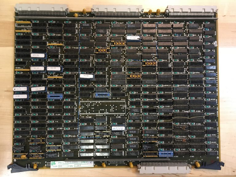
The RG, CM, MI, and DP boards together contain the logic for the Lambda’s Lisp processor, one specially designed to run Lisp code efficiently.
Lambda CPU: RG “Registers” board

This system is outfitted with two sets of these boards. This was a way to make the system more cost (and space) effective: A single Lambda could run two processors and two consoles (and thus service two simultaneous users) while sharing a single disk. Since Lisp Machines were typically single-user machines, reducing the overall cost and footprint in this way would make the LMI more attractive to buyers concerned about investment in very expensive computers. (Symbolics did something similar with their 3653 workstation: it contained three 3650 Lisp CPUs in a single chassis.)
Lambda CPU: MI “Memory Interface” board.


The logic in the Lambda is built entirely from 7400-series TTL (Transistor-Transistor Logic) parts along with a few PALs (Programmable Array Logic) and EPROMs (Erasable-Programmable Read-Only Memory). The most complicated IC involved is the 74181 ALU used on the Data Paths board. The 74181 was a 4-bit ALU used in many processors of the time, though it was a bit outdated by the time of the Lambda (The Xerox Alto used them way back in 1973, for example).
Lambda CPU: DP “Data Paths” board:
 note the 3×3 array of 74S181 ALU chips.


That’s good news — TTL, PAL and EPROM parts are still readily available so they can be replaced if they fail. The trick, of course, is being able to debug the hardware to the point where the bad chips can be accurately identified. At the moment, circuit schematics are not available so this will likely be a challenge.
Lambda CPU: CM “Control Memory” board

The Motorola 68010-based UNIX CPU Board,
for when you want to contaminate the beauty
of your Lisp Machine with UNIX.

The “CPU” board in slot 11 contains a Motorola 68010 processor and allowed the Lambda to run UNIX alongside Lisp. This configuration, with two CPUs and the 68010 UNIX board, was referred to as the 2×2/PLUS. (See the exciting product announcement here!)


The VCMEM boards each drive a single high-resolution terminal — a black and white monitor into which a keyboard and mouse plug in, connected to the Lambda by a very long cable. (The terminals typically lived far away from the Lambda itself since no one would want to work very close to a machine this loud.) I got two consoles with the machine, but only one keyboard and mouse, alas.
VCMEM board — framebuffer memory and display, keyboard, and mouse controller

16MB of memory

The memory boards provide memory for the Lisp processors to use. Each processor can address up to 16MB of memory.
System Diagnostic Unit


The SDU sits in the middle of the cardcage and acts as a middle-man, so to speak: it negotiates communication between the NuBus boards on its right from the Multibus boards on its left. Additionally, it is responsible for booting the system and can be used to run diagnostics, to format drives, and to reinstall the operating system from tape. It is based around the Intel 8088 CPU.
Multibus Interphase SMD 2181 Drive Controller, in carrier.


The Multibus controllers sit in special carriers that adapt the boards to the form-factor that the Lambda’s card cage uses. The disk, tape, and ethernet controllers were off-the-shelf parts made by other manfacturers: 3Com for the Ethernet controller, Ciprico for the Tape controller, and Interphase for the Disk controller.

From the looks of things, everything is in the right slot, except for that TI Memory board in slot 20. That’s a Multibus slot and the Lisp memory boards won’t work there at all (and in fact could end up getting damaged if installed there when power is applied). Someone likely put it there to keep the board safe while in storage or in transit. I removed that board and put it in a static-proof bag for safekeeping.


The misplaced Texas Instruments-manufactured memory board, easily distinguishable by its use of surface-mount rather than through-hole parts.

Board Inspection and Cleaning

While going through the card cage I took every board out for inspection and cleaning. Things to look for are severe amounts of dirt, dust, rust or corrosion, physically broken or burned components, damaged circuit board traces, bent pins, and other things that don’t belong on a circuit board.

Socketed chips are good to look at closely: the sockets and the pins on the ICs are more prone to corrosion in my experience (not entirely sure why — some of this is due to being more exposed to the elements than soldered-in chips, moisture may linger in the sockets for a longer time than elsewhere; it may also be partially due to reactions between the different metals used in the sockets and the IC pins). On these boards it was not at all uncommon to find chips like this:
Fairly corroded legs on an Intel 8089 I/o Coprocessor

Light oxidation manifests as a dull grey patina on IC legs and socket connectors; corrosion as more obvious orange or brown rust or green verdigris. Any of these will cause poor connection with the sockets and must be eliminated. Oxidation and corrosion can usually be removed with some fine-grit sandpaper or gentle scraping with a sharp X-Acto knife blade. Sometimes such cleaning will reveal legs that have corroded away so much that they fall off — which is always disappointing to find. This fortunately has not happened to any of the ICs in the Lambda so far.

Occasionally you run across something like this:
IC with a bent leg found as-is in a socket!

This is more common than you might think — the pin got bent over when placed in the socket when the board was manufactured, but still made good contact with the top of the socket pin so the fault was never discovered. Over time, this can cause intermittent failures. Luckily it’s pretty easy to bend these back without breaking them.

And then sometimes you find something completely inexplicable:
How’d that screw get there?


I have no idea how or when this happened, but that screw was very firmly wedged in-between those two ICs. Given that the boards are vertically oriented in the chassis, it seems really unlikely that a screw fell in the top and managed to get stuck in there. Very strange. Also not good for operational integrity. Note also the grey oxidized pins on the blue socket in the lower right of that picture. When new, those were shiny and chrome. Luckily that’s a spare socket and is unused.

Inspecting the Rear Chassis

The logic boards plug into the front of the chassis. Around back, there’s another set of connectors which small “paddle cards”plug into, breaking out signals into cables that connect to peripherals and run to bulkhead connectors like these:
The back of the CPU card cage. Some light pitting on the aluminum of the rear panel.


That rear panel hinges outward and reveals the rear side of the Lambda’s backplane:
Behind the rear panel

You can see how the backplane is segmented here: On the top running from right to left you have the NuBus portion, which ends on the left with the NuBus Terminator paddle card. (There is a similar terminator on the right side as well). On the lower-left you can see two sets of four slot backplanes for the CPU interconnects. To the right of those are the paddle cards for the VCMEM slots: These bring out the connections for the high-resolution terminals, which are cabled to DB-25 connectors on the bulkhead panels. Further to the right you can just make out the SDU paddle card. Everything to the right of the SDU slot is Multibus — the middle section of these slots carry the Multibus signals, while the top and bottom sections carry device-specific signals for disk, tape, and ethernet cabling.

The important thing to check here is that all the paddle cards are present, in the right places, and are in decent shape. This appears to be the case. All the cabling looks to be intact as well. Good news all around.

Conclusion

After a lot of careful inspection and cleaning, the Lambda’s chassis looks to be in solid shape. In my next installment I’ll go over the power supplies and fans, and do the first power-up of the system. See you then!


Monday, June 15, 2020

At Home With Josh, Part 1

[Editorial note: I originally wrote this series of blog posts for LCM+L's ENGBLG. Since LCM+L is shutting down for the foreseeable future, the fate of ENGBLG is uncertain.  I am in the process of translating these posts over to my personal blog in an attempt to preserve this content.  - JD]

A Tour of my Workspace


Like many of you, I’ve been spending most of my time at home these days. While the museum is closed to the public, the engineers and other awesome staff are hard at work planning future exhibits and tours, polishing up our on-line systems, and working on hardware and software projects from the comfort of their couches. Or in my case, a workbench in the basement.

While I’ve been working from home, I’ve been hacking on a bit of emulation on the Unibone, archiving a huge pile of 8″ floppy disks and doing some preparatory research for a future emulation project. But I thought some of you might be interested what I’ve been working on in my spare time, which, as it turns out, is mostly identical to what I would usually be doing in my day-to-day when on site at the museum.

I have what might charitably be called a “hoarding problem” and as such I have ended up with a tiny computer museum in my basement that I’ve been adding to for the past twenty or thirty years. What started as a couple of Commodore 64s and TRS-80s (and so, so, so many TI-99/4As) scavenged from garage sales for $5 a pop when I was eleven has grown to encompass micros, minis and a few supercomputers crammed into an ever-shrinking space in my basement. Over the years I’ve learned to restore and maintain these systems, and since starting work as an engineer at LCM+L, I’ve gained even more knowledge but I still have a lot more to learn. In my spare time I tinker on machines in my collection, getting them to work again and making them do stupid/clever things.

So, here’s a brief tour of my basement museum, after which I’ll introduce you to my current restoration project.

Look at that fine wood paneling.


Starting on the left-hand end of the west wall, we have an AT&T 3B2/600G UNIX system (1986) on top of a DEC PDP-11/73 (1983) and MicroVAX-I (1984). A classic LSI ADM-3A terminal adorns the 3B2. The PDP-11/73 was the first DEC system (and first minicomputer, even though DEC referred to it as a micro) I acquired, when I was still in high school. At the time it was running Micro-RSX, now it runs 2.11BSD. The large system to the right is a DEC VAX-11/750 (1980) with TU80 9-track drive. The 750 is restored and when I need to heat up the room, it runs 4.3bsd-Quasijarus or VMS. There’s currently a Data General Dasher D200 terminal on top of the TU80; it’s awaiting the completion of an Eclipse S/230 system.
Even more computers!  Blinky lights!


Moving further to the right, the DEC and Data General equipment continues: In the left rack I have a 1971 Data General Nova 820 (well, it’s a Canadian “DataGen” system but apart from a faint maple syrup smell…) on top of a DEC PDP-8/I (1968) with an OEM front panel. The Diablo 30 belongs to the Nova and has yet to be restored. In the right rack is a PDP-11/40 system (1973), with two RL02 removable pack drives (capacity 10mb) and one RK05 drive (capacity 2.5mb). The 11/40 runs a variety of systems: RT-11, RSX, Ultrix-11, and I plan to play around with RSTS on it sometime in the not-too-distant future. The PDP-8/I is in working condition but currently lacks peripherals beyond the basic teletype interface.
PDP-8s abound.


Continuing our tour, we are confronted with even more DEC equipment. The Straight-8 on the left is one of my favorite systems and I’m incredibly lucky to have found it. The Straight-8 is the first of the PDP-8 line, introduced in 1965. This particular unit is serial number 14, making it a very early example of this system (about 1500 of this model were made). It is nearly fully restored — there is a random glitch in the teletype interface that causes it to hang at random times and I haven’t yet tracked down the cause (though I suspect an intermittent backplane connection.) The next rack contains my workhorse PDP-8: a PDP-8/m with TU56 DECtape drive, RX02 floppy drive, RK05 removable pack drive and PC05 high-speed paper-tape reader and punch (these latter two are currently obscured by the ASR33 Teletype sitting in front of them). At the moment I have TSS/8 running on it.
Computer potpourri.


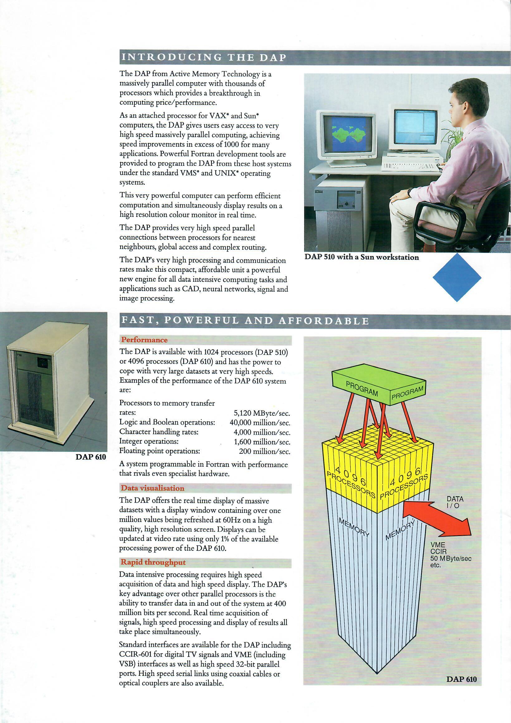
The next rack to the right contains a miscellaneous assortment of minicomputers in various states of repair. From top to bottom: Texas Instruments 990/4 (1975, Data General Nova 800 (1971), Texas Instruments 980B (1974), PDP-8/e (1971), and mostly hidden is a Bunker Ramo BR-2412 (1971), an obscure 12-bit system originally manufactured by Nuclear Data. Tucked away in the corner is an AMT DAP 610, c. 1990. This is a massively parallel array processor, sporting 4096 1-bit processors in a 64×64 array. Each processor runs at 10Mhz, has its own memory and can communicate with its immediate neighbors via high-speed links. The system is capable of 40 billion boolean operations per second. It’s also technically a SCSI peripheral! The front-end processor for the DAP is a run-of-the-mill Sun Sparcstation LX.

North Wall: Way too much stuff.

Progressing along the north wall, we have a smattering of systems and terminals, the most notable being the Inmos ITEM (“Inmos Transputer Evaluation Module”) which contains 40 Transputer processors, the PDP-11/34 (1977) which I’m using for Unibone development while working from home. The Tektronix 4051 computer and 4014 terminal are really cool examples of Tektronix’s Direct-View Storage Tube technology. The blue system in the corner is what remains of an Imlac PDS-1D (with front panel console box in front) and in front of that is a small rack with an Interdata Model 70 processor in it. Way back in the corner are shelves full of calculators and miscellaneous items too numerous to cover in detail. Also it’s a mess over there, and I try not to look at it too long. Avert your eyes…

Ridge 32 and VAX-11/730


Along the east side of the basement are a couple more systems: A Ridge 32 Supermini and a VAX-11/730. The Ridge 32 (1984) is an early 32-bit RISC design designed to be a VAX killer but hobbled by its operating system, ROS. ROS was a UNIX-alike system and at the time that just wasn’t enough, despite the system’s extremely fast CPU. The VAX-11/730 (1982) is one of my favorite systems — it’s the world’s slowest VAX at slightly less than 1/3 the speed of the original VAX-11/780 (0.3 VUPS) but it’s small, relatively quiet, and clever — The entire VAX processor was compressed into three hex-height boards. A couple of years back, I took this system to the beach:


VAX on the beach.

Where it ran for 5 days providing dial-up service at 300 baud and a splendid time was had by all. We only tripped the breakers a few dozen times and it only rained once…

Where was I?

LispM's, PERQs, and Suns.


Next up along the east wall is a collection of workstations; from left to right these are: Symbolics XL1200 (1990), Symbolics 3630 (1986), Three Rivers PERQ 1A (1981), and a Sun 2/120 (1986). The Symbolics systems are part of a class of systems known as “Lisp Machines” (LispM’s for short). They are near and dear to my heart — sophisticated systems from a lost era of computing. The PERQ 1A is a computer that came out of Pittsburgh in the early 1980s — a graphical workstation inspired by the Xerox Alto with local storage, a high resolution (768×1024) display, ethernet, and a microcoded CPU. It was an immensely clever design and was a very powerful machine for the time (and for the price) but Three Rivers never quite figured out how to compete in the market against Sun, Apollo and others. It is quirky and strange and hacked together, and I love it so much I wrote an emulator for it way back in 2006
The middle row of computer junk.


Finally we have the center row of benches where I have a few notable systems set up, including two currently slated for restoration: a Xerox Alto and an LMI Lambda. I picked these two up on a recent trip out east, and they are two systems I never thought I’d own. I’m really looking forward to restoring them both, and my plan is to document the restoration here on this blog over the coming weeks. I’ve chosen the Lambda for the first restoration — I love the Alto more than just about anything else in my collection (I even wrote an emulator for it) but there are already several restored specimens in the world (including at LCM+L, of course) and there are, at the time of this writing, no LMI systems in operating condition in the world. (The Lambda in my basement is one of six known to exist.)
A Bit Of Background on LMI and the Lambda

The history of Lisp Machine Incorporated (LMI) and of lisp machines in general has been written about fairly extensively in various places (see here and here) and this post is running a bit long already, so I’ll provide an abridged version in this post:

In the mid-1970s a group of hackers at MIT’s AI Lab designed a series of computer systems for the specific purpose of running Lisp programs efficiently. The first was known as the CONS, and its successor the CADR was a sufficiently successful design that it was proposed to create a commercial product in the nascent Lisp AI space. Opinions differed on the best course of action and so two competing endeavors ensued: Lisp Machine Inc., and Symbolics. Both companies started off selling commercialized versions of the CADR (LMI’s as the LMI CADR, Symbolics’s as the LM-2) before expanding off into their own designs. Symbolics emerged the victor: their follow-up to the CADR, the 3600 series, was extremely successful while LMI struggled to sell their Lambda workstation — fewer than 200 were sold. LMI went bust in 1987 before it could produce its Lambda successor, the K-Machine.

My Lambda


My Lambda came out of a drafty Pennsylvania garage it had been sitting in for over twenty years. It was covered in a fine grit of mouse droppings, dust, and bits of shingle from when the garage’s roof was replaced several years back. It also has a fine patina of rust and corrosion on nearly every surface.
The Lambda, in all its glory.

It’s also missing the tape drive and disk drive. The good news is that both of these are at least somewhat still possible to find: The tape drive was a standard Cipher F880 9-track drive with a Pertec interface, and the hard drive was a Fujitsu Eagle SMD drive. It’s likely that any Pertec-compatible tape drive will work, and it should be possible to find a suitable SMD disk that still functions.


Apart from the missing drives, the system appears to be complete: The backplane is fully populated with boards and in fact is a 2×2-PLUS system (two LISP CPUs and a 68010-based UNIX CPU in one chassis!). Two consoles were included with cabling, but only one keyboard and mouse, alas.


There were once gold-plated connectors on this RJ11


Dirty LMI Mouse


Lookit that rust!


Complete Lambda card cage


More rust!


LMI's adaptation of the MIT "Space Cadet" keyboard.


Two Lambda consoles, prior to cleaning.


Restoration Plan


So my hope is to restore this system to operating condition, and since I’ll be here at home a lot more than usual I’ll have ample spare time to do it in! As I progress in the restoration in my off hours I’ll post updates here to keep you all in the loop and to give you an idea of the kind of steps we typically undertake when restoring systems at LCM+L.

It’s important to have a plan for this sort of thing; so here’s my current plan of attack, which is of course subject to change depending on how things go:
  • General cleanup. After twenty years in the garage, this thing smells fairly musty and as mentioned previously, is quite dirty. The chassis, consoles, cables and all assorted ephemera need to be cleaned out and inspected for damage. If mice get into computer hardware they can do serious damage. I haven’t seen any evidence of this but it’s best to be sure.
  • Inspection, cleaning, and testing of the system power supplies. Just plugging a system like this in after so many years lying dormant is a bad idea. The supplies will be removed from the system, checked out and tested with dummy loads prior to reinstallation. Any necessary repairs to the supplies will be undertaken at this time.
  • Inspection and cleaning of the boards in the backplane, and the backplane itself. This entails cleaning of corroded pins on socketed ICs and inspecting for serious damage.
  • Power up of a subset of boards, starting with the SDU (System Diagnostic Unit). The SDU can be used to inspect and test the rest of the boards in the system, once a tape drive has been procured.
  • Find a working tape drive and disk drive; write out a copy of the LMI Installation and System tapes.
  • Use the SDU to test the rest of the boards in the system.
  • Restore one or both of the Lambda consoles; use the SDU to test them.
  • Install the system to disk.
  • Boot the system.
  • Do a dance of some kind.

Daniel Seagraves (author of LambdaDelta, a most-excellent LMI Lambda emulator) is undertaking a similar effort as I type this; he rescued two Lambdas from a much worse garage than the one mine came from and is documenting his restoration efforts here. We’ve been chatting and he’s been extremely helpful in inspecting my Lambda and has sent me some updated SDU ROMs and an Ethernet interface for my system. His help will be instrumental in getting my system going.

Whew. I think that’s enough for one blog post. The next post will bring everything up to date with the current status of the restoration.